Digital Tachometer
How I made a digital engine tachometer for my vehicle.
Overview
I own a 2000 Chevy S10 with an automatic transmission. In order to, I assume, cut production cost, the stock version did not come with an engine tachometer. Although it's not strictly needed, being an automatic, this gave me an excuse to attempt to build my own.
I wanted it to be a challenge, however, so I decided to do it without using a microcontroller (for example, an Arduino).
Theory of Operation
My setup imagines an encoder on the engine flywheel that would produce 1 or more square waves per revolution. These pulses would be counted by several binary counters. There would also be a real time clock (RTC) that would reset the whole thing at a regular period.
The potential challenge of such a setup is that it seems that it needs some way to calculate Revolutions-Per-Minute from the binary counts it's receiving. Naturally, this would be trivial with a microcontroller. What I decided to do was contrive the setup so that each binary counter would store a single decimal number. They would be externally programmed, with logic gates, to clear when they reach 10 and carry out to the next counter. I could also control two other variables: the "counts-per-revolution" and the clock period. With a clock period of 0.25 seconds and a counts-per-revolution of 24, the number of counts received in that interval will equal RPM/10. this meant that I could acheive +/- 10 RPM of accuracy without doing complex calculations. The numbers from the counters would simply be fed into registers, then the registers to 7-segment display decoders. I drew up some schematics, picked some components, and soon had my first design.
First Design
This design suffers an unfortunate flaw. It was caused by me not reading the binary counter documentation closely enough. It has to do with the function of each counter clearing itself when it reaches 10. It detects this case with an AND gate on the QB and QD outputs. It produces a rising edge to clock the next counter. It also goes through an inverter to produce an inverted logic signal to for the CLR function.
However, the RTC clock must ALSO be able to clear ALL the counters. To solve this conflict, instead of adding a logic gate to the CLR input (I opted for this later), I chose to use CLR for the RTC-clear, and use the LOAD input for the self-clearing function (intending for it to load 0000). If I had read the documentation more carfully, I would have learned that the LOAD function does not affect the outputs until the next CLK cycle! Meaning that every 10 clock cycles the counter sees, it misses 1! Thus, in each stage, we have a loss rate of 1/11. I learned all this after I soldered it up and debugged it with an oscilloscope. The lesson is: read the documentation.

Schematic of the main circuit for the tachometer.
Schematic of the optical encoder.
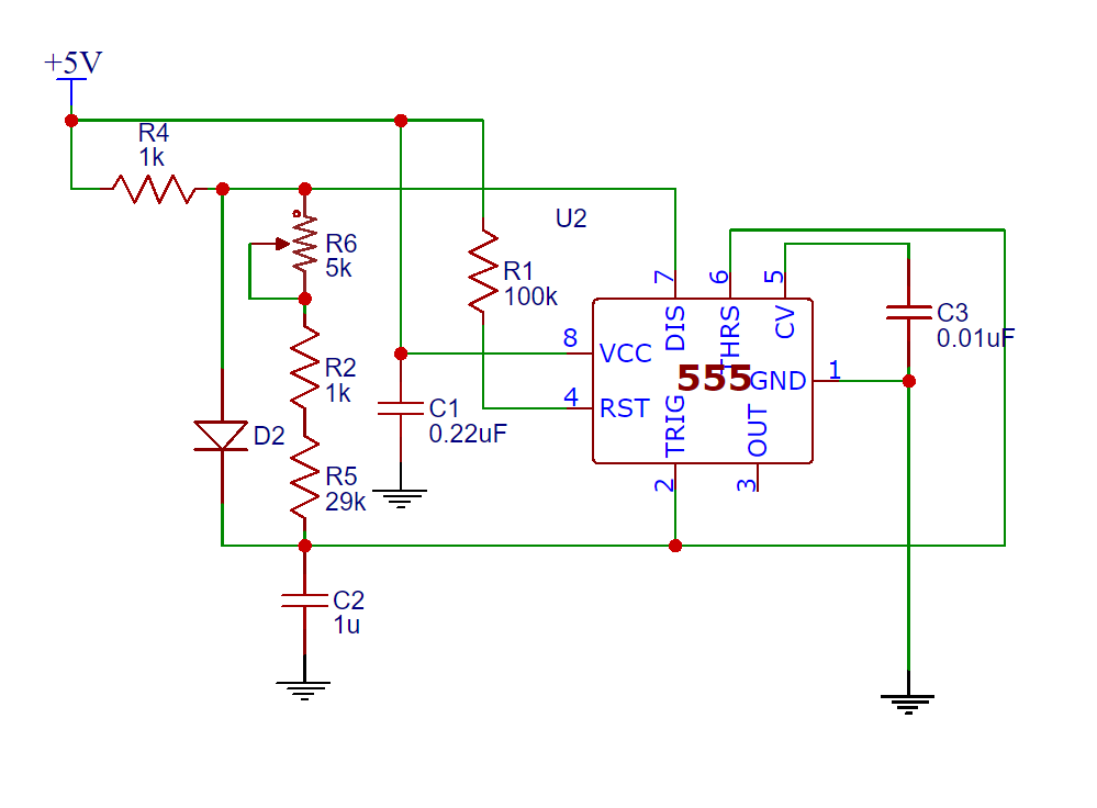
Schematic of the 0.25 second real-time-clock built using a 555 timer.
Second Iteration (Fix)
I eventually got around to fixing the issue outlined above. I added a quad-2-input NOR gate, and I was able to lose the inverters, and instead used one of the NOR gates as the inverter I needed for the RST/CLR/LE signal from the 555 timer. I also removed the redundant registers present in the first design (the 74xx4511's have internal latches). The circuit schematics are below, and I have made most of the design available as an EasyEDA project.
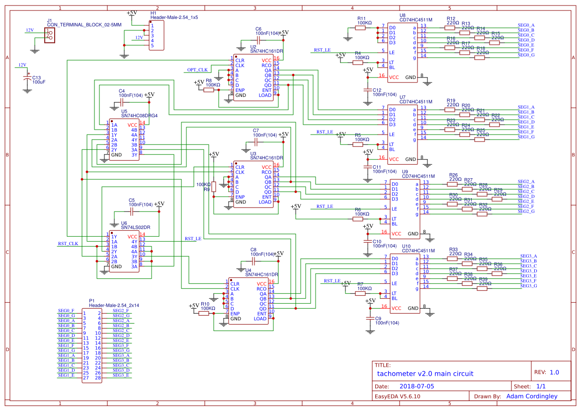
Schematic of the main circuit for tachometer v2.0.
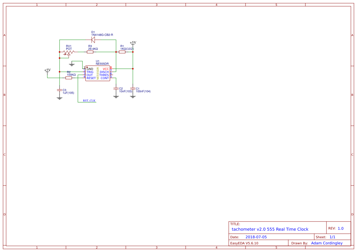
Schematic of the 555 real-time-clock for tachometer v2.0.
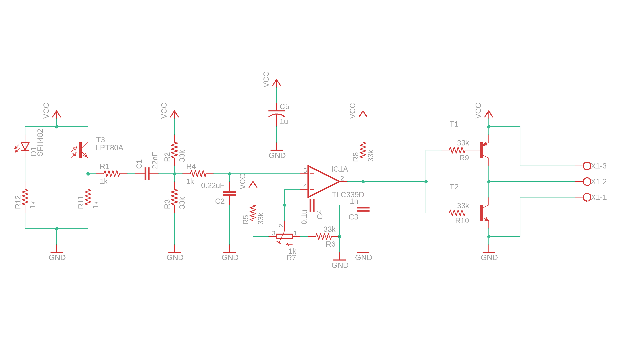
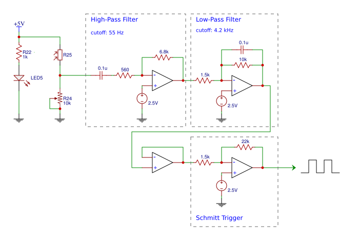
Schematic of the new encoder for tachometer v2.0. This was drawn in Eagle CAD, so is not on the EasyEDA project page.