Automatic Mains Switch
Power a secondary load when a primary load is detected
Overview
I initially got this idea from a project by woodworker John Heisz who built an automatic mains switch. That design is a bit better than his earlier design. His circuit is nice and simple, but a few things I don't like about it are that it requires around a 10A load to trigger the secondary circuit, it requires a special large-ish transformer, and it can only successfully trigger a solid state "relay". This is all fine I guess, but I wanted to try my hand at a similar switch that would trigger at lower load current and energize an electro-mechanical relay, meaning it could be adapted to switch a DC load or signal another device if desired.
December 2021 Update
Sometime in 2021, I was sitting around bored and came up with an idea I liked better, that is in some ways more straightforward. As long as we have to use an op-amp, let's just sense the current with a shunt resistor instead of fooling around with transformers and whatever. I thought it would be nice to make it all solid-state this time, which makes it smaller and lower power potentially.
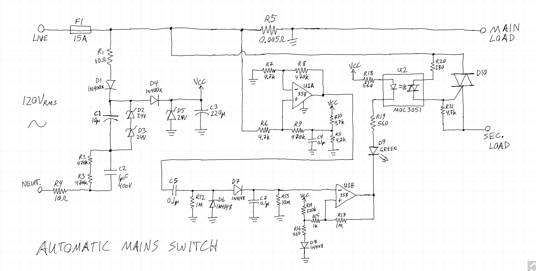
New schematic for my automatic mains switch circuit.
Based on simulation, this circuit will trigger the secondary with only a few hundred milliamps flowing through the main load. I think the niftiest (most unique?) part of this circuit is the power supply. I came up with it for another offline powered projet where I needed a power supply that basically was boosted above the live rail. It's one I've not come across anywhere else.
The schematic speaks for itself, but bascially you have a typical capacitive dropper driving a charge pump. I find it easier to think about by setting Live as the "0V reference", and imagining Neutral swinging up and down. So when Neutral swings negative WRT Live, It charges C1 to ~48V max. Then when Neutral swings positive WRT live, C1 is boosted above Live, and the charge in C1 is transferred to C3. When C1 is discharged, and D2 and D3 conduct, excess current through C2 is dealt with by D5.
If you don't believe it would actually work, let me tell you that I've built it, and it totally does work. It feels a bit crude and naughty, but it gets the job done.
Original Idea
I wanted to use a simple current-sense transformer and detect a load using a peak-detector circuit. I found a small toroidal inductor core, around which I wrapped several turns of 14 AWG solid-core copper wire as the primary and a dozen or so turns of 22 AWG solid-core wire as the secondary. I then put together the following circuit:
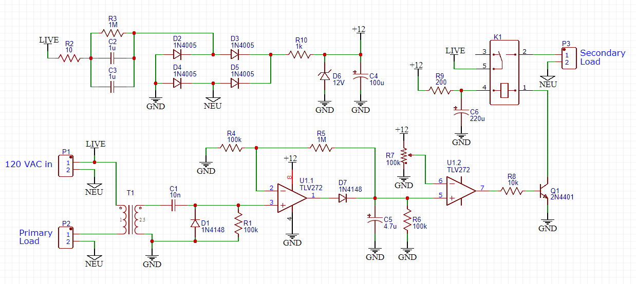
First concept for my automatic mains switch circuit.
The power supply is as simple as it gets using a capacitive dropper, a bridge rectifier, and a 12V zener diode. The capacitive dropper, C2 and C3, should use class Y film capacitors for safety, and R2 additionally should be a fusible resistor. A MOV wouldn't be a bad idea either. The user will never be touching or interacting with any part of this circuit, which is why I think this approach is OK.
The signal from the transformer can probably only supply minimal current. Fortunately our DC restorer, 100kΩ resistor, and 1pA op-amp input barely load it down. This signal is then amplified 10x and put through a peak detector circuit. The second half of the TLV272 is configured as a simple comparator with an adjustable threshold.
I'm using a neat trick for switching the relay. My relay coil's DC resistance was ~150Ω which would draw ~80mA in it's on state – too much for my low-power circuit. Like most relays, however, it only requires so much current when switching on, and once on it can stay on with less than half of this initial current – ~30mA in my case. This is often called the holding current. To achieve this, I include C6 to provide the initial switch-on current. Once on, R9 limits the current to ~33mA.
In terms of power usage, the TLV272 takes about 1.1mA. The current required to drive any external loads is minimal. The BJT base will draw about 1.1mA. The relay is the biggest power user, in my case using ~33mA when on. Safe to say the entire circuit will draw maybe 35–40 mA.