Multi-Channel Electronic Load
A large electronic load for high power things
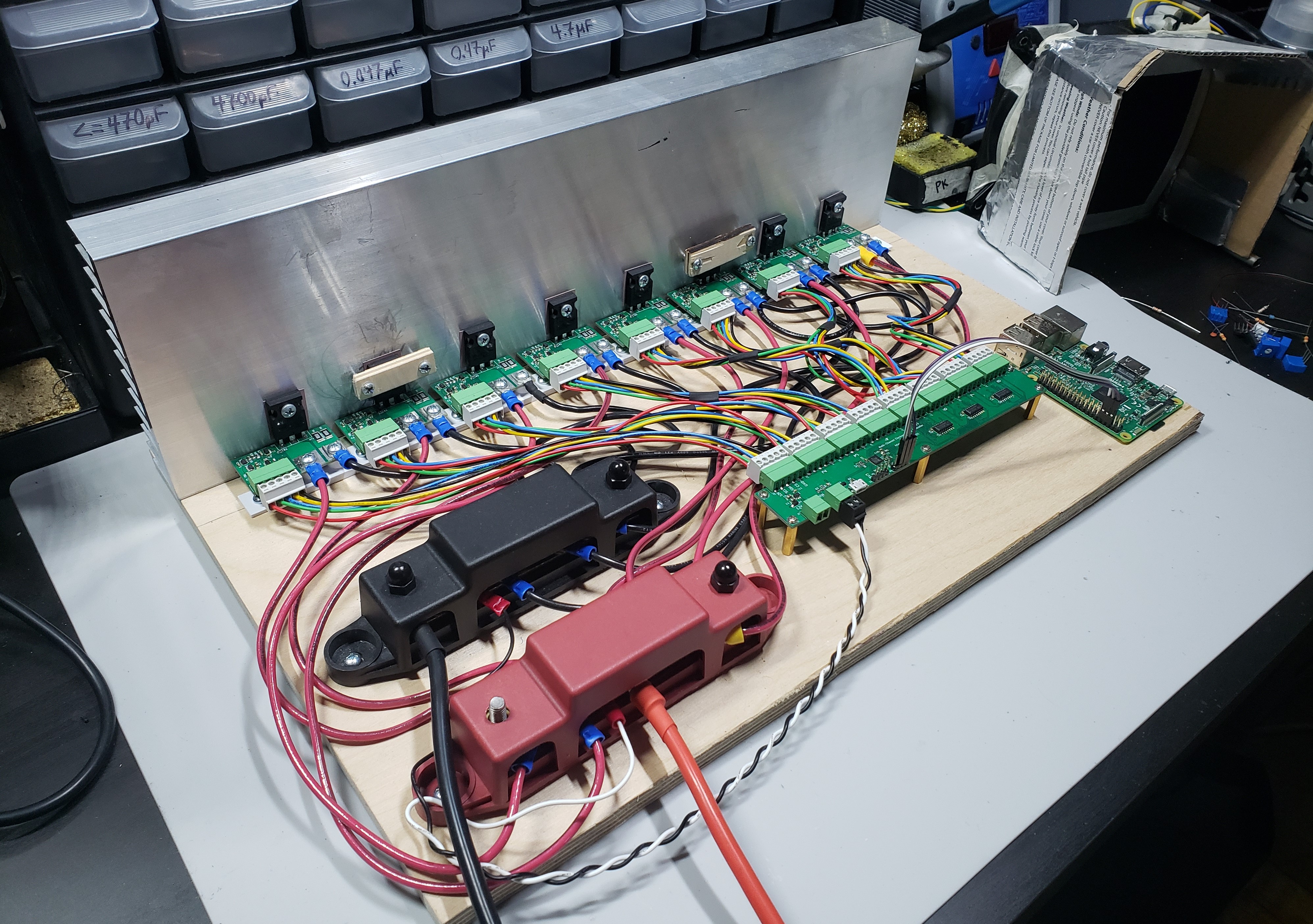
My 8-channel electronic load.
Links
How much power, you ask? Well that's a good question. I haven't yet fried any of the components, but at around 350W, the MOSFETs get "pretty hot", so I haven't pushed it much beyond that point. I'm probably just being paranoid. I designed the whole system to handle up to around 48V in, and each module can be set to sink about 19A at full scale. Of course whether or not a module's transistor can actually survive 19A for very long depends on the applied voltage.
Theory of Operation
The electronic load is built from 8 modules/channels controlled by a single control board. Each module has a 10-bit DAC which sets the current set-point, a shunt resistor and a chopper amp to sense the current, and an op-amp to drive the gate of a power MOSFET. The module also has a 3.3V linear regulator to provide a locally regulated supply and reference for the DAC and chopper amp.
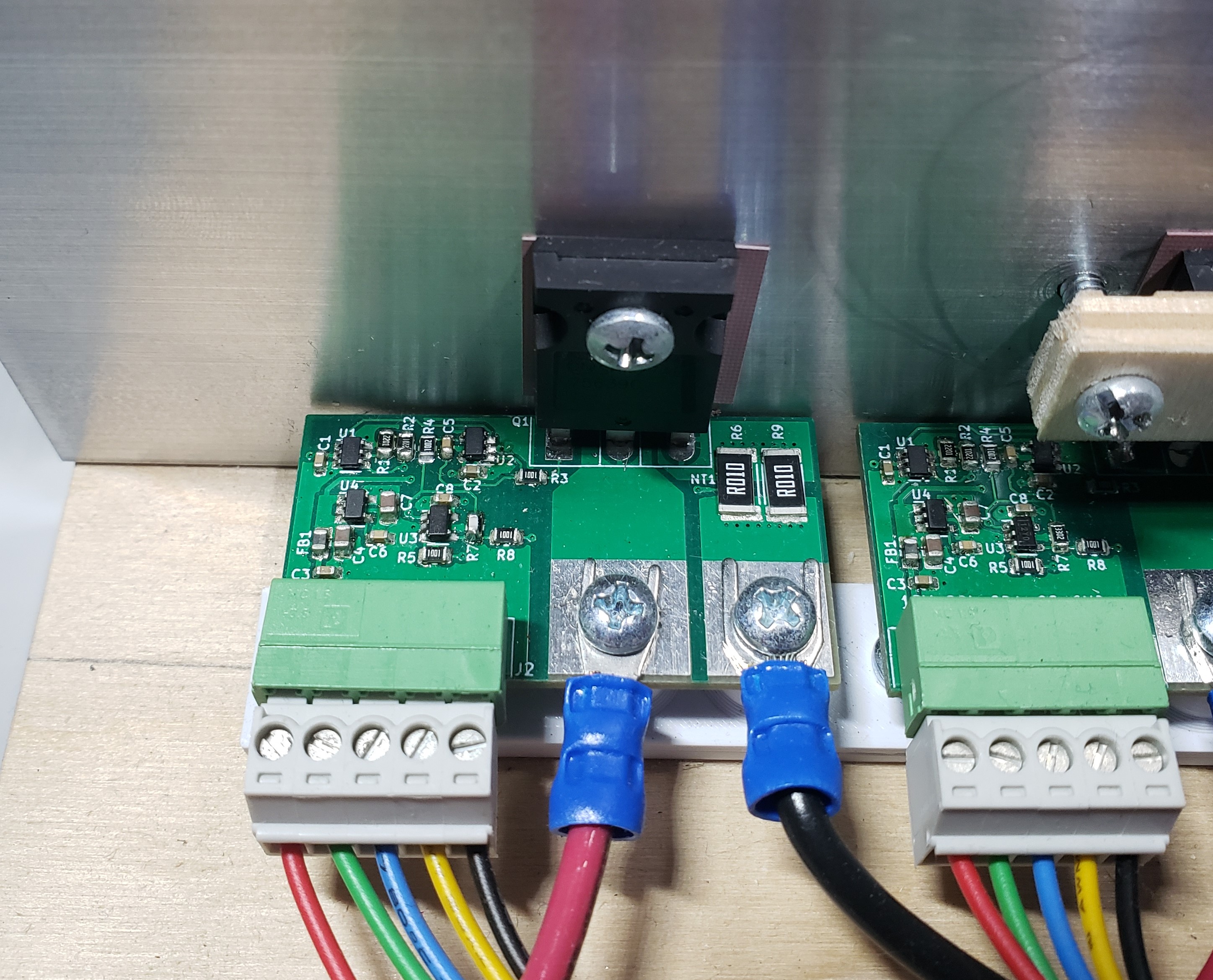
Close-up of one of the modules/channels.
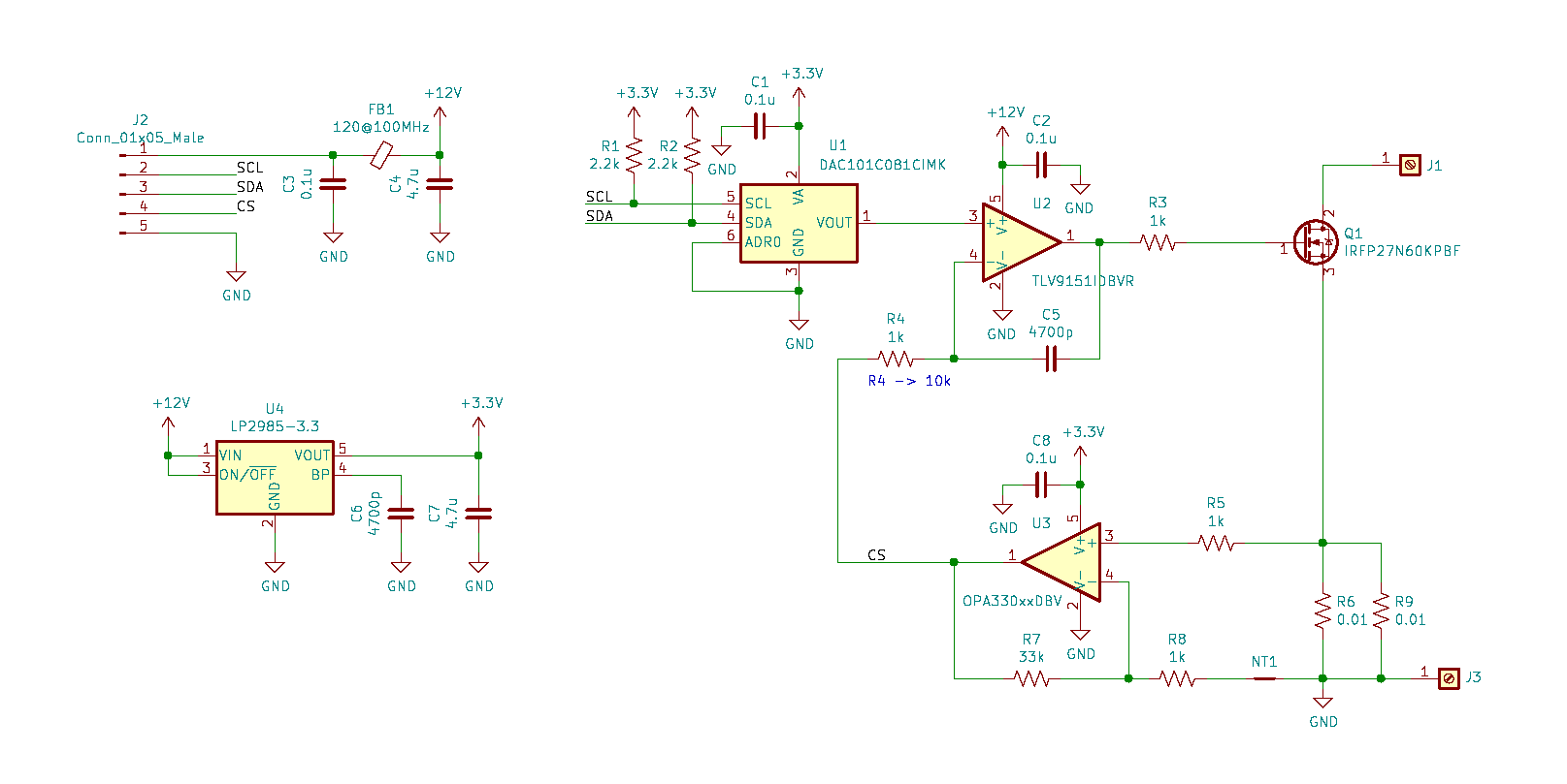
Schematic of a single electronic load module.
The controller uses an STM32L432, which I bought before the chip shortage got bad. It also has a few 74HC4051 muxes which it uses to continuously scan across all eight channels, one-at-a-time, setting the current over I2C and sampling the current-sense voltage with the built-in 12-bit ADC. It's also responsible for sensing the voltage that's presumably applied across each module, simply with a resistive divider and another ADC channel.
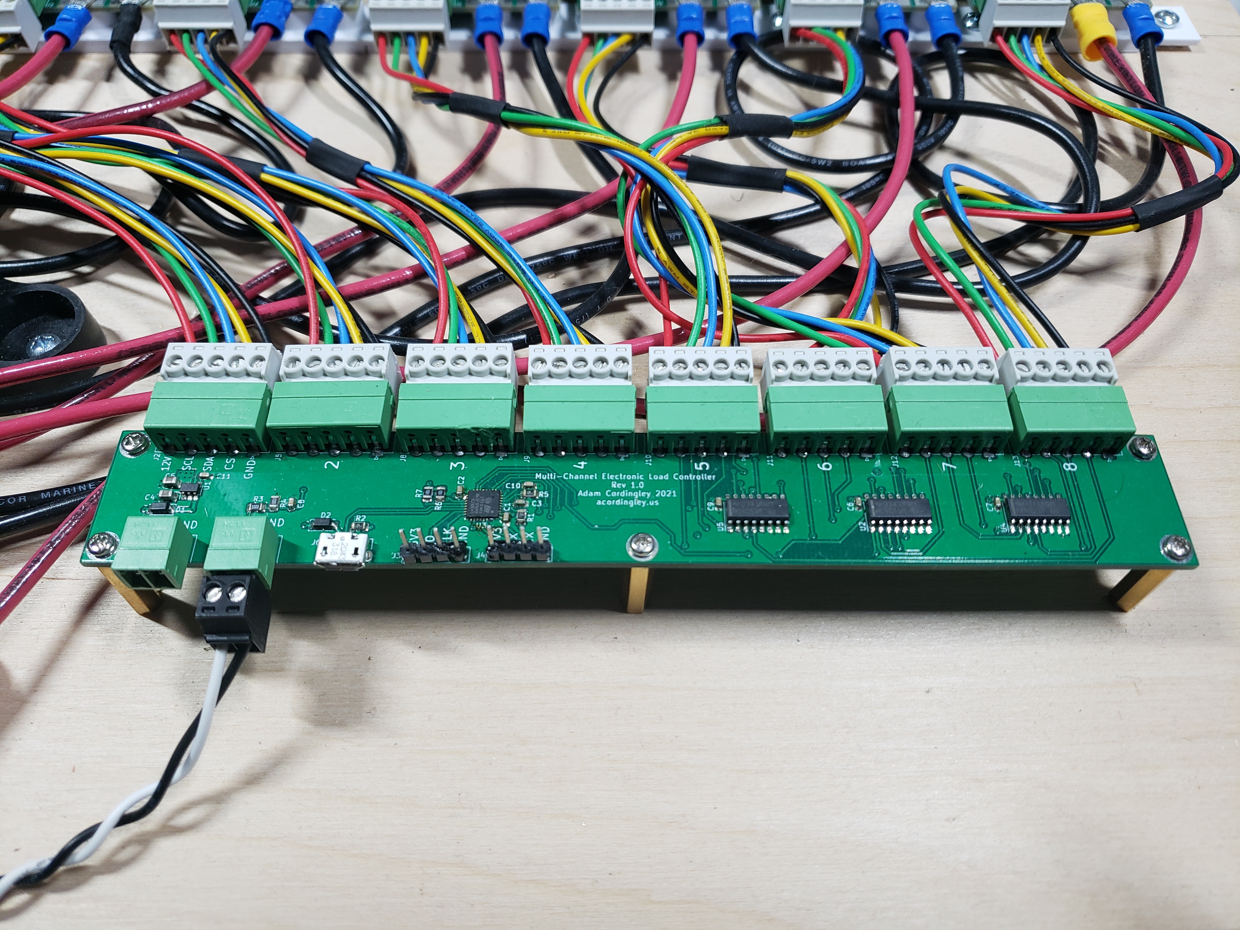
The electronic load controller itself.
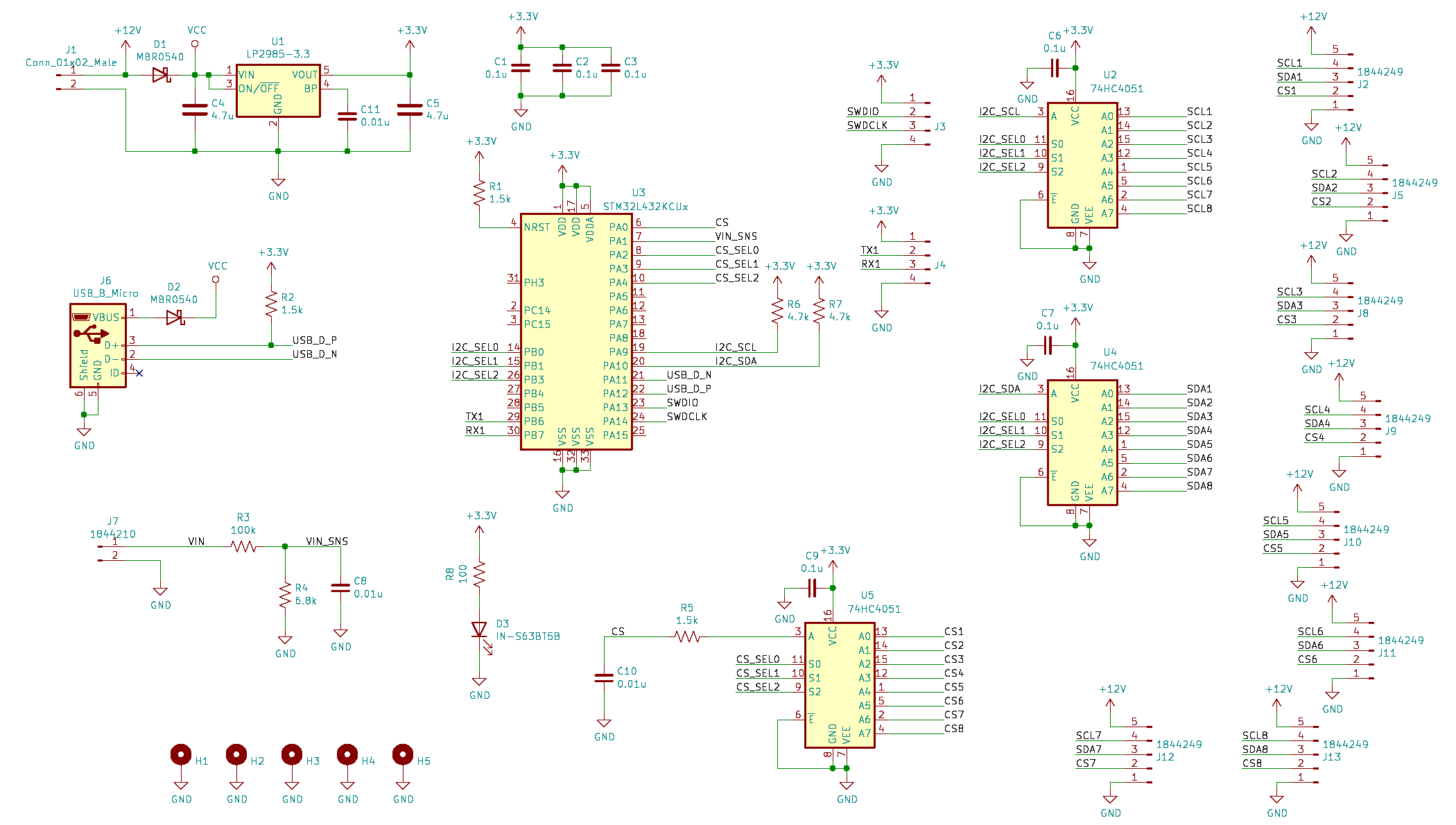
Schematic of the electronic load controller.
Software Control
The controller is communicated with via UART using SCPI commands. It was going to be over USB, but I ran into "mysterious" problems with the USB connection and decided to switch to UART to move the project along. I decided to build a web app using flask and angular JS. The flask part runs on a raspberry pi. The RPi serves up a webpage and the angular JS part runs in a browser.