Amateur Radio
KE8ITF
I'm a general-licensed amateur radio operator (callsign: KE8ITF). I have more info on my QRZ profile.
Table of Contents
High-Altitude Balloon Project 2023
Purpose and Overview
Payload Source Files Github Repo
I'm building a payload for a high-altitude balloon. The payload will transmit location, barometric pressure, and temperature data on the amateur radio 2m band and act as a APRS beacon. I decided to do this the hard way and build the whole radio and everything "from scratch." That is mainly what this blog post is about, the purpose being a sort of notebook documenting my design process, and to serve as help for others attempting to do something similar.
Primary Goals:
- Make measurements and collect data.
- GPS location
- Barometric pressure (also second rough determination of altitude)
- Temperature (inside and outside payload compartment)
- Telemeter data on the Amateur Radio 2m band (144.39MHz)
- Log the data to on-board, non-volatile storage (micro-SD card).
- Powered from NiMH batteries.
- Take some pictures and whatever.
Payload Hardware Design
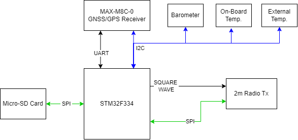
Payload logical overview block diagram
For the main processor, I chose the STM32F334C8T6, primarily because it has the HRTIM peripheral, which is a high resolution counter clocked from a delay-locked loop at over 4GHz. This enables sufficiently fine control of the PWM frequency while running at a few MHz. The reason this matters is because I wanted to generate the baseband signal directly from the microcontroller, and feed it straight into the analog part of the radio transmitter. More on this later.
The sensors were whatever I found through a little google and digikey parametric searching. The GPS Receiver is the u-blox MAX-M8C-0 - a fairly popular module that looked easy enough to work with. I chose an on-board GPS antenna, and called it a day there. Didn't really need to be anything fancy, just enough to work.
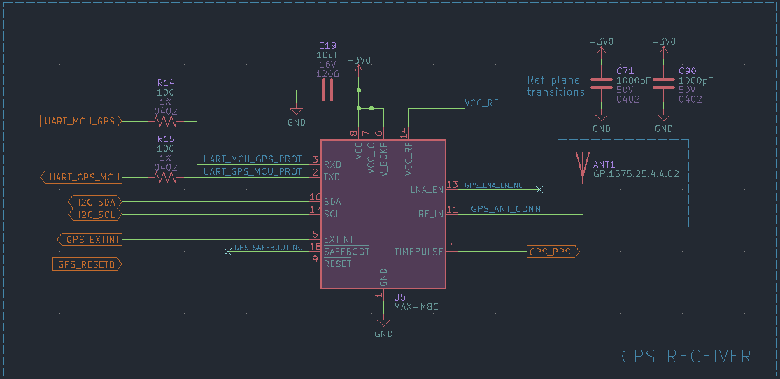
GPS receiver schematic screen-clip.
The two temperature sensors are the MCP9808, which are IC's which feature +/-0.5
The barometric pressure sensor is equally uninteresting, just whatever I found on digikey that would read a low enough pressure.
Radio Transmitter
The radio transmitter is a little more interesting. It's sort of a single-up-conversion, superheterodyne architecture. Except the modulation to create the IF is done in the microcontroller, all digitally.
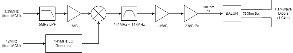
Payload radio transmitter block diagram
I want to build a basic half-wave dipole as the transmit antenna. They're simple to build and simple to understand, and can work quite well with little effort. One of the chief issues with this is the feedpoint impedance at resonance is ~73Ω (call it 75Ω). Our system impedance - per tradition - is 50Ω. This mismatch means we don't have maximum power transfer. Many radio amateurs simply live with this situation - I guess because they have plenty of transmit power and a good 'nuff receiver - so the mismatch doesn't matter enough in most cases. (The VSWR in a 50Ω system feeding a 75Ω load is ~1.5. The casual HAM is likely happy with any VSWR less-than ~2.)
$$ \Gamma = \frac{Z_L - Z_0}{Z_L + Z_0} $$
$$ VSWR = \frac{1+|\Gamma|}{1-|\Gamma|} $$
Link Budget
In my design however, I don't have a ton of transmit power to work with. I designed for ~28dBm on a good day. Let's round this out to about 0.5W or ~27dBm. Let's also consider a few dB of loss/mismatch, then consider some weak gain from the dipole. For this SWAG, let's say it washes out and our EIRP is ~27dBm. Is this going to be enough? Let's do the math!
The radio I have on hand specs 0.18μV @ 12dB SINAD, which is basically saying that a signal of 0.18μV amplitude at the receiver can produce intelligible speech. In reality, let's say the minimum receivable signal is actually like 0.25μV (some margin would be nice). What dBm does this correspond to?
$$ P = \frac{0.25\mu V^2}{50\Omega} = 1.25\cdot 10^{-12} mW $$
$$ P = 10\cdot \log{(1.25\cdot 10^{-12})} = -119 dBm $$
This result, somewhere around about -120dBm, seems about right based on my experimentation with my Baofeng. I'm gonna kinda do this backward and figure out, based on these numbers, the max distance appart the transmitter and receiver could be and still work. As before, for this SWAG, I'm going to assume that the weak antenna gain washes out with the losses in the matching network(s) and such. That makes this really simple! Our calculation looks like the free-space-path-loss between two ~isotropic antenna situations. Thus:
$$ \lambda = \frac{c}{f} = \frac{2.998\cdot 10^8}{144\cdot 10^6} = 2.08m $$
$$ FSPL_{MAX} = 27dBm - (-119dBm) = 146dB $$
$$ FSPL_{MAX} = 10\cdot \log_{10}\Big(\Big( \frac{4\pi d}{\lambda}\Big)^2\Big) $$
$$ d = \frac{\lambda}{4\pi} \cdot 10^{FSPL_{MAX}/20} = 3.3\cdot 10^6 m$$
I'll admit, 3 300 km distance sounds pretty ludicrous. But the math for this does check out. I don't think I'll see anywhere close to this kind of performance, but the fact that in an ideal world, it could work like this, bodes well for my much humbler goals (maybe ~33km or so). If we think about that, that's 2 orders of magnitude in base 10 less distance, which means I'll have about 20dB of margin in the link budget. Which is a good place to be I feel.
Antenna Matching Network
With all that "will it work on paper" stuff out of the way, we can get into some actual design. As discussed above, we need to match a 50Ω system to a ~75Ω load. I prefer to do the matching on-board. Thus, with a simple PI matching network, I end up with a single ended 75Ω output. Which is not matched to most 50Ω cable :(. This is fairly easy to solve since it's only operating at one frequency. So if we know our cable, then we know the wavelength of our signal in said cable, and as long as I make the 50Ω feedline a multiple of λ/2, then the 75Ω feedpoint impedance will be translated unperturbed to the output of the matching network. Or so goes the theory.
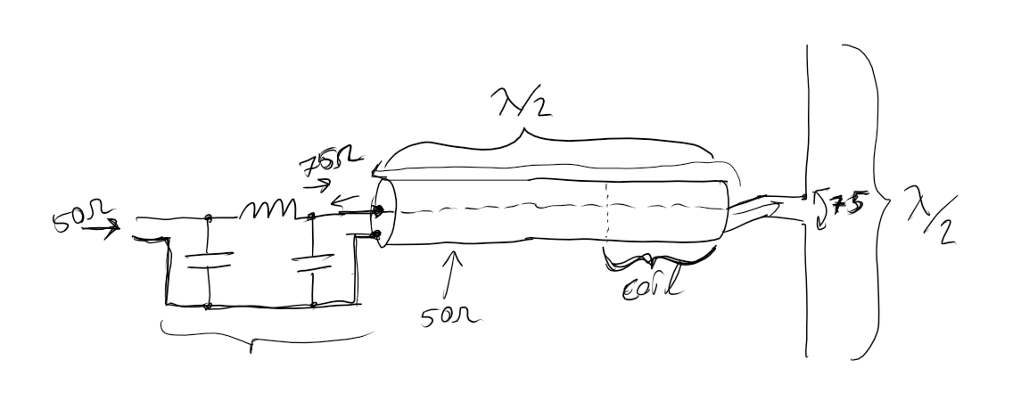
Crude schematic of the plan for the feedline and antenna impedance matching.
There's one other little detail that many radio amateurs also tend to neglect. That is the dipole, to radiate efficiently, needs a balanced impedance feeding it. It kinda makes intuitive sense I hope, so we'll just leave it there. (Note: you can get away with not doing this, but the feedline itself becomes part of the radiating element, which can produce unexpected effects.) So we need to turn a single-ended impedance into a differential impedance. This can be done with a balun formed by coiling up a few turns of the feedline into a "common-mode choke", which is a type of transformer (a 1:1 current balun). So with the same N*λ/2 length feedline, I'll create a few turns with the last 20cm or so, and form a neat, weatherproof balun. No funny-business necessary.
Power Distribution
I plan to power this off a 2s NiMH battery. To do anything with this, the ~2.4V needs to be boosted up. I boost it first to 8V, since 8V is needed for the final power amplifier (PA). Then I buck convert it down to ~3.0V and 5V. Pretty simple.
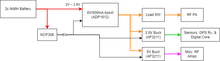
Payload power architecture block diagram
Payload Firmware & Software
As mentioned in the hardware section, the payload is run by an STM32F334C8T6 microcontroller. It is capable of generating the several-MHz IF signal needed to upconvert to the carrier frequency of 144.39MHz.
APRS <== AX.25 <== HDLC <== NRZI <== AFSK
I'm mostly going to take a bottom-up approach to this problem. I'll start with how to form 1's and 0's using AFSK, then work on forming bytes and packets. At some point I'll branch off and write some higher level framing stuff, then work on APRS level stuff. I'll document my process here.
The structure of the system is roughly thus: APRS uses AX.25, which uses High-Level Data Link Control (HDLC) for framing. Bits are encoded using NRZI encoding. Then the two states (1 and 0) are formed using Audio Frequency Shift Keying (AFSK).
Forming 1's and 0's (NRZI)
According to the Wikipedia, AX.25 transmits its HDLC framed data using NRZI encoding. Wikipedia, as usual, also has a good intro to Non-Return-to-Zero Inverted (NRZI). AFSK defines two baseband frequencies that you shift between to form symbols. NRZI means that each symbol is encoded by a transition - a shift - in your baseband audio signal. So a mark tone or a space tone don't map to 1 or 0 per-se (that would be NRZ, typical for RS-232 style UARTs). It's the transition between these two states that defines the value of a bit. It's still an exercise to the designer of a system to decide whether a transition is a 1 or a 0. The other little detail that arises is the need for bit-stuffing, but I'll address this next.
APRS
The APRS Spec.First Article Bringup
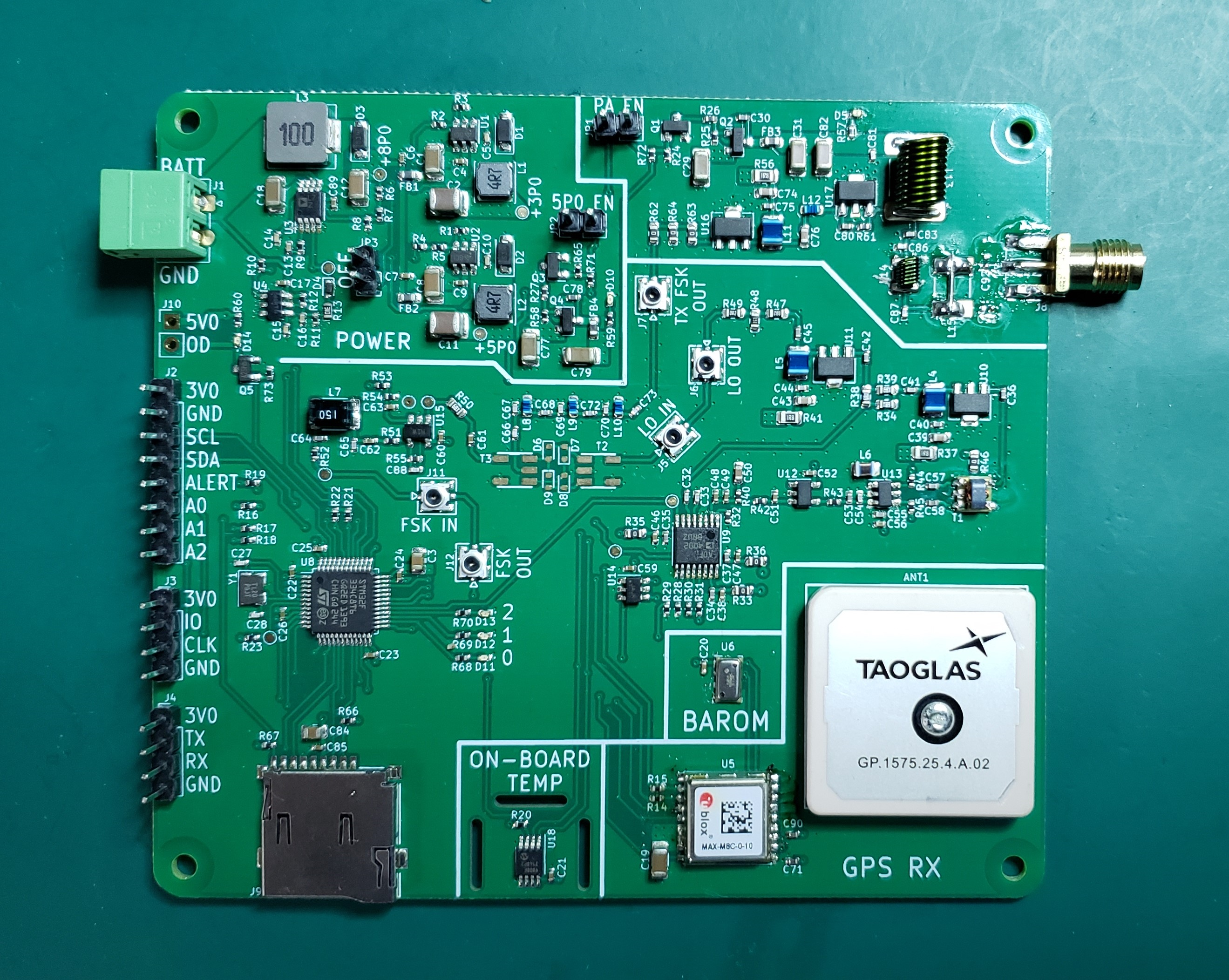
Photograph of the first article PCBA, missing only the mixer components.
Lots of things worked great right away. With V-BATT = 2.4V, all power rails came up. Doing nothing, it drew around 60mA. Once the digital core and GPS receiver were doing their respective activities, the current draw was nearly 200mA. Enabling the LO circuitry (the PLL and some RF amps), current draw was around 0.5A. All-in-all, a little more power hungry than I was hoping. But it's what ya get I suppose. LO generation looked pretty good. I could talk to all the devices on the board. Initially however, the GPS receiver couldn't get a strong enough signal, at least on the bench in my apartment in downtown Seattle. It could usually see at least one satellite, and sometimes could see enough to theoretically get a fix, but the signal was reported as being too weak to be usable. At the time of writing this, I haven't brought it outdoors to try it. That's the next step.
SD Card Driver
The STM32CubeMX software provides the FatFS middleware to do filesystem-level things. The work left to the user is to write the low-level driver that talks to whatever storage media they choose. This is the SD card in my case, talked to over SPI. The SD card driver creation was made pretty easy by this article and the associated github repo, owned by github user kiwih, from which I copied the parts that do the SPI things with the SD card, including the necessary SD card commands and whatnot. Many thanks to kiwih!
RF Section
LO Generation
The LO looked servicable, and was only ~14ppm off-nominal. Considering the crystal that's generating the 12MHz reference (G3212000182080) is ±20ppm @ 25oC (and additional ppm's over full temperature range!), this is a within-spec result. (That crystal is apparently discontinued at LCSC, but I somehow got it turnkey assembled from JLCPCB.) In truth, it would be worth swapping in a better crystal - a real pro-gamer move would be to use a proper TCXO. But I didn't think about all this until too late. I suspect that ±20ppm is probably good 'nuff for this purpose (channel widths are over ~10kHz = ~70ppm, and also does every cheapo radio have a TCXO in it???), but we will see.....
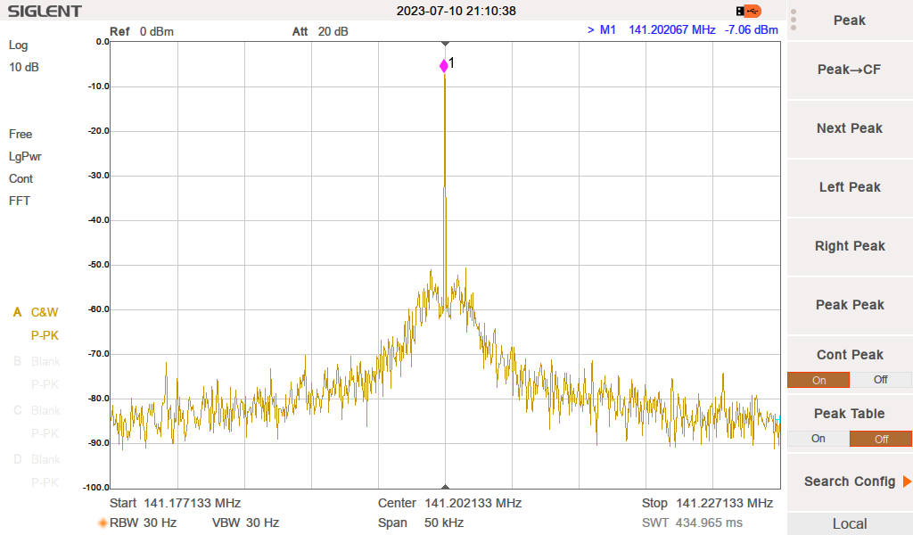
Spectrum of the LO output, fed through a 10dB attenuator into the Siglent SSA3021X.
The LO was a little weaker than I was planning on. I was hoping for at least 6 or 7 dBm of drive strength for the mixer. Instead, we're seeing about 3dBm. Fortunately, I have a ~3dB pad in the signal path that I can remove and jumper out. What all this means is either (1) I'm not getting the full gain I was hoping to get from the PGA-105 gain blocks, or (2) the CX2045 balun is lossier than expected. Working backwards from our result of 3dB at the LO GEN OUT port, it's easy to see that we are getting -18dBm out of the VCO (assuming the amps are operating with nominal gain). The VCO (MAX2606) allegedly can put out -10dBm, though a reactive power match may be required to realize that. This configuration works, but a future optimization may involve simply replacing the 1k pull-ups (R44 and R45) with small inductors.
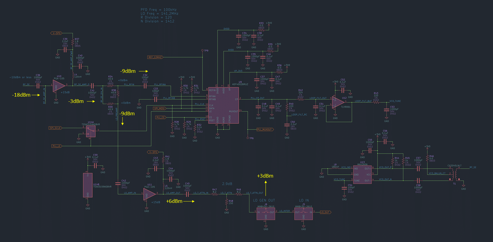
Schematic of the LO generator circuit, with annotations for power levels at various points.
Mixer Performance
The upconverter as a whole was disappointingly lossy. After the mixer and filter, the resulting power was about -35dBm. Quite a bit less than I was hoping for.
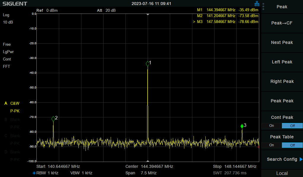
Spectrum analyzer screenshot showing the output of the J7 connector, after mixer and filter.
I soldered in some wires and made a crude measurement directly at the output of the mixer (before the filter), and found it to be at about -15dBm. This was closer to what I was expecting there and shows that the filter is losing about 20dB in it's passband! Not great, but ya can't win em all I guess. What this means is I'll need an additional PA to get this to some transmittable level. Which I kinda was thinking I might do anyway, but this makes it more of a necessity.
What I will take as a win was the good LO rejection. The LO falls a little bit in the passband of the filter, so what we're seeing there is all LO rejection. Not too bad! This tells me that I could actually bring the baseband FSK signal and LO closer in frequency and get better definitions of mark and space frequencies. Good!