Mains Load/Source Balancer
A device for balancing a load between two sources
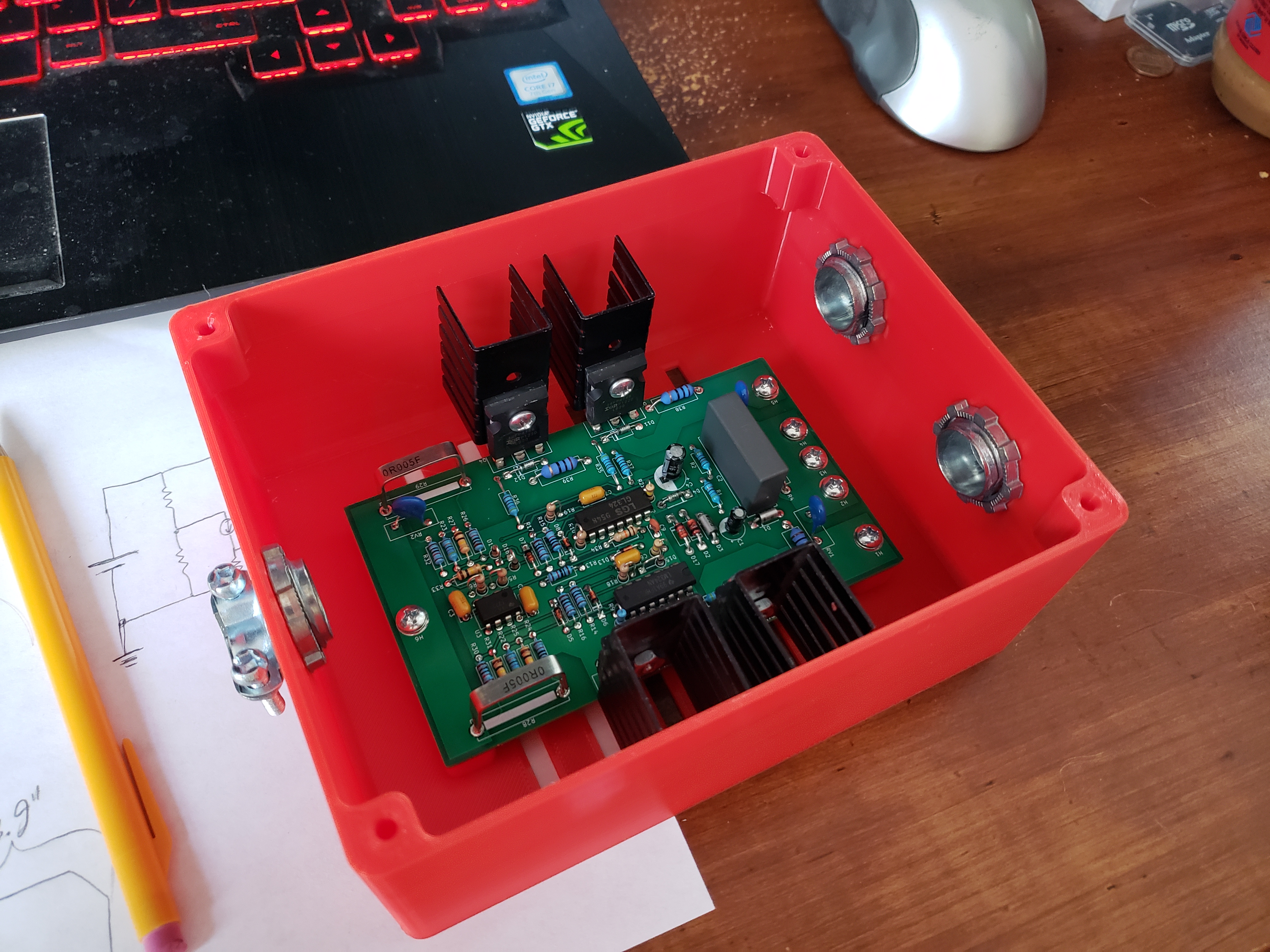
The load balancer in a box.
Don't Build This...
On today's episode of "things you probably shouldn't go and build" we have the load balancer. It really should be called the "source balancer," but I initially called all the files "Load_Balancer..." and so I felt I had to stick with it. Unless you know what you're doing with mains voltage, and understand the risks you're taking, DON'T build this. I make no guarantees about this circuit. With the disclaimers out of the way, let's get into it!
The Problem
The problem goes like this: I have some load that will draw upwards of 20A, but all the power outlets in my rental are supplied from 15A breakers. Plus they're loaded with other things, so I'd be pushing it to draw even a whole 15A from any one outlet at any point. So what if I wanted to basically connect two outlets on different breakers together, hoping to only pull 10A from each one? Would it work? Let's analyze a hypothetical case.
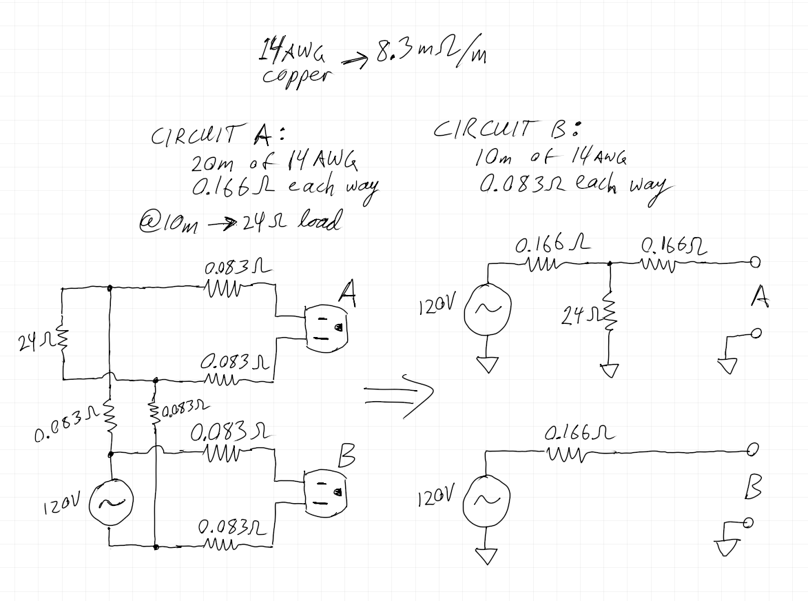 My current rental is wired with 14AWG wire, and I guesstimate anywhere from 10 meters to 30 meters of wiring exists between the breaker box and a given outlet. Also in my hypothetical case, we have a moderate 24 Ohm load on circuit A drawing around 5A, just to add another factor to the mix. In my analysis here, I lump the resistances of live and neutral together for each circuit, so I don't properly account for the return paths being tied together, hence in parallel. But this error is pretty marginal (I simulated it to check).
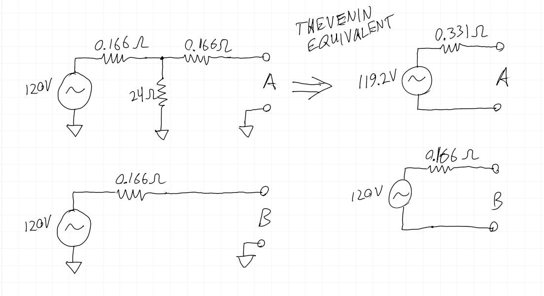 So we take the thevenin equivalent of circuit A, and we find that there's quite a bit of resistance appearing between our outlet and a slightly lower-than-desired voltage source.
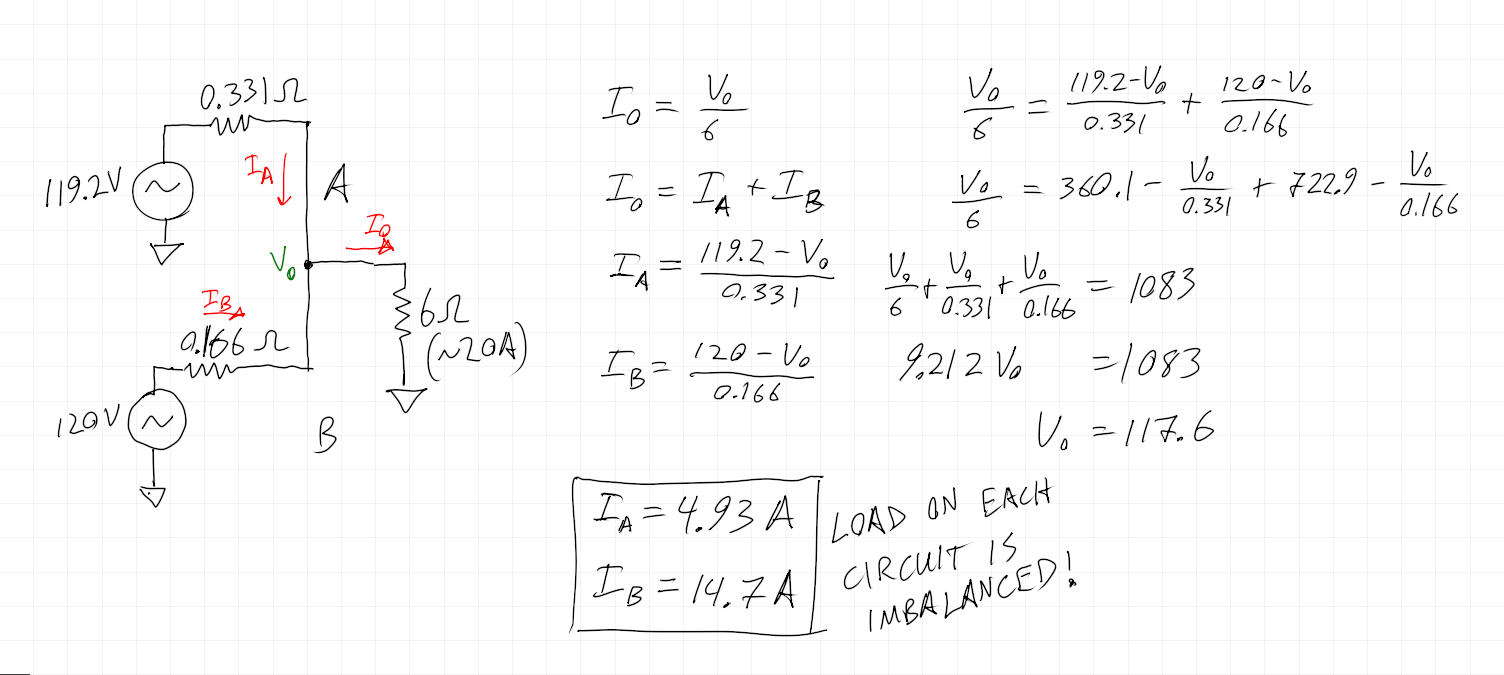 After some messing around with circuit math, we finally get the result: circuit B is taking about 3 times the current of circuit A! And we're still pretty close to tripping circuit B's 15A breaker. So this little exercise hopefully illustrates why you may not get away with simply tying two circuits together in "parallel" to try to handle heavier loads.
The First Solution
So what if we had some circuit that could actively adjust the current being drawn in these 2 paths to make them match? I figured I'd take a crack at it, and eventually came up with what you see below.
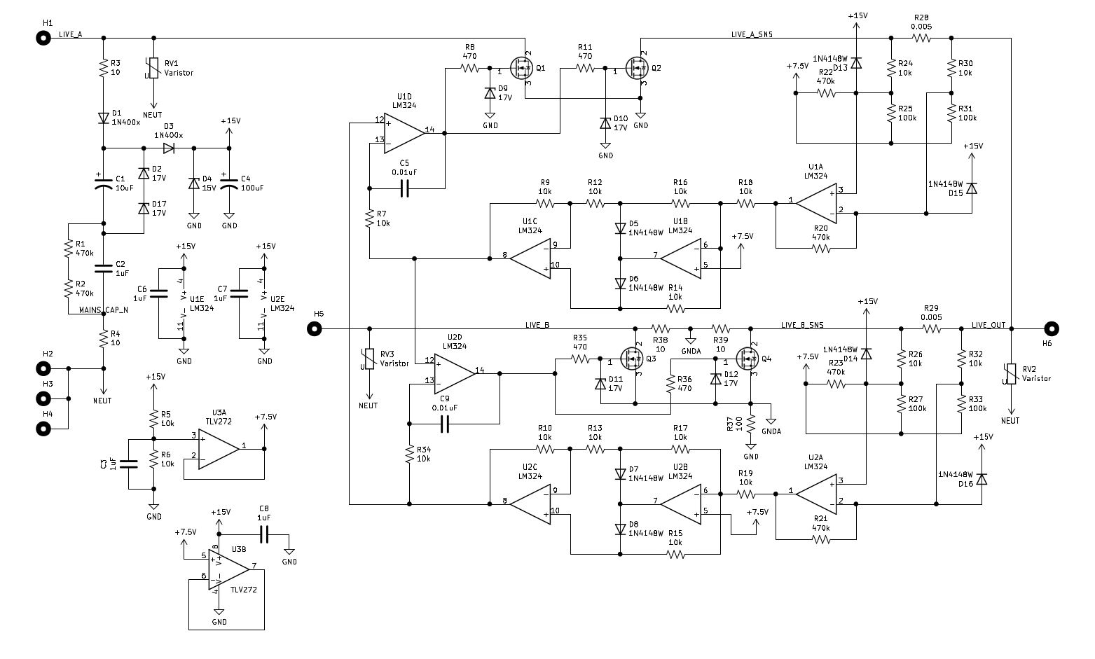
The full schematic of the load balancer.
The back-to-back MOSFETs allow adjustable, bidirectional current flow. Current in each path is sensed by a 0.005 Ohm shunt. The amplified shunt voltage is biased to half the supply, around 7.5V. This voltage is then rectified and the 7.5V bias subtracted away. This is the current sense feedback for each path. This feedback is used as the setpoint for the opposite side, and so the two reach a happy equillibrium. In order to kickstart the current flow (in the case where both sides are just sitting at 0A) I've added R38 and R39 to begin trickling current through path B, starting the feedback loop.
Results
But does this really work? Well, yes, but there are drawbacks I didn't quite consider, the big one being power dissipation. Let's go back to the example above and think about what's going on for a moment. Basically you can imagine we have 2 current sinks/sources with their outputs commoned together. This current regulating effect is achieved by modulating the MOSFET's RDS. So the circuit regulates down the higher-voltage, lower-resistance side by turning on those MOSFETs less. Resulting in power dissipation. This is easier to explain with a drawing. See below:
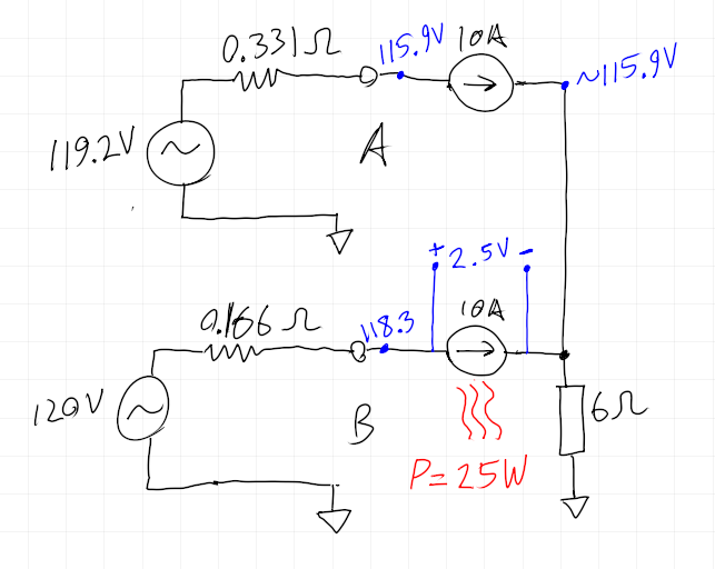 As you can see, using our hypothetical scenario from above, inserting this circuit ends up with 25W dissipation on one path. This heat will be split between the two MOSFETs on that side, but at 12.5W each, they're still gonna be cookin. I didn't plan for this, but I put on the biggest heat sinks I had on hand (which aren't very big), and I guess I'm just gonna hope for the best until I can get some bigger ones.
Finally, here is a top view of the assembled board. I opted for a through-hole design because I had a quite a few THT components in the design, and I had lots of THT components on hand, so it made sense.
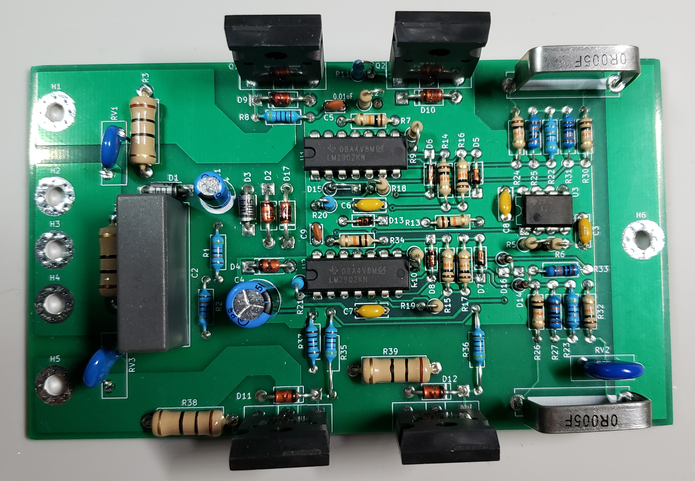 The big thing I forgot in this design was an LED!
An Alternative Power Supply
After I did all this, I realized that the power supply could be a bit simpler. We need a supply that's positive when referenced to Live. Well we have AC input, so why not just assign "Live" as "ground", and imagine that Neutral is swinging around Live? Then we could draw the following circuit:
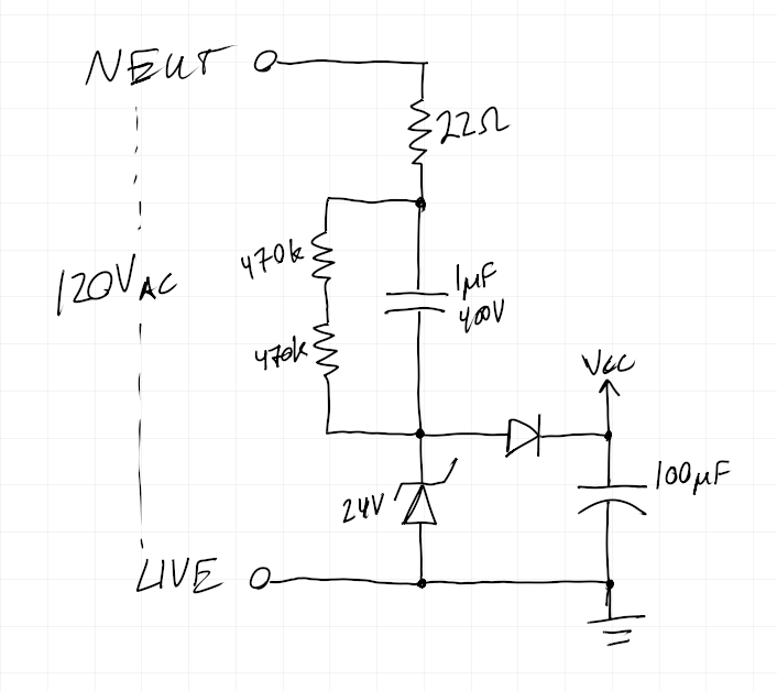 At the end of the day, what's a few capacitors and diodes between friends? Well, minimizing points of failure is always a good thing, and I believe this simpler circuit would work. So, I guess, if you build this circuit, you might want to use this power supply instead.
The Second Solution
When you're talking about tripping breakers due to drawing too much current, what you're concerned about is average current over time. This is because the mechanism that trips the breaker is a bi-metalic stip which heats up with current flow. As more and more current flows, the heat increses, it deflects more, and eventually trips the breaker. So a 15A breaker can handle brief periods of, say 20A or 25A. The higher the current, the more brief that period needs to be.
The idea I had was a circuit that alternates between one circuit and the other. So for one cycle of the mains sine wave, it would switch on only circuit A and draw full load current from A. On the next cycle it would switch on only circuit B, and draw full load current from B. And It would keep alternating like this, so the average current that each circuit sees would be half the full load current. And the losses in the switches would be minimal since we could switch in each circuit at the zero crossing of the sine wave.
To the drawing board!
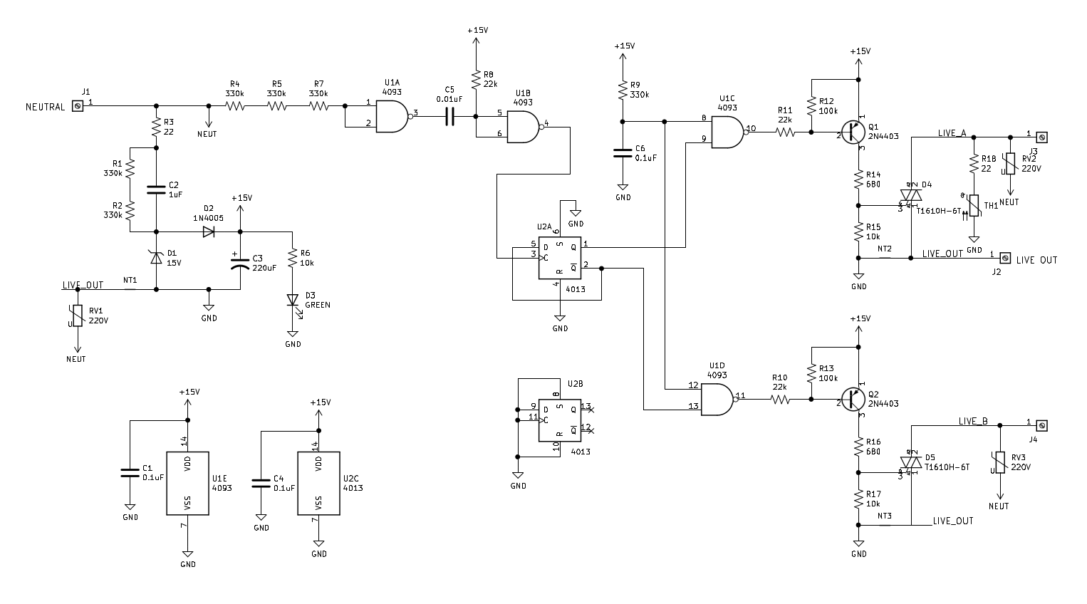
The full schematic of my new idea for a lower loss load balancer.
I haven't tested this one yet, but wanted to put it on here before I posted this article. Results update will follow!