Modular Multiphase Power Supply Unit
A 2.4kW Power Converter
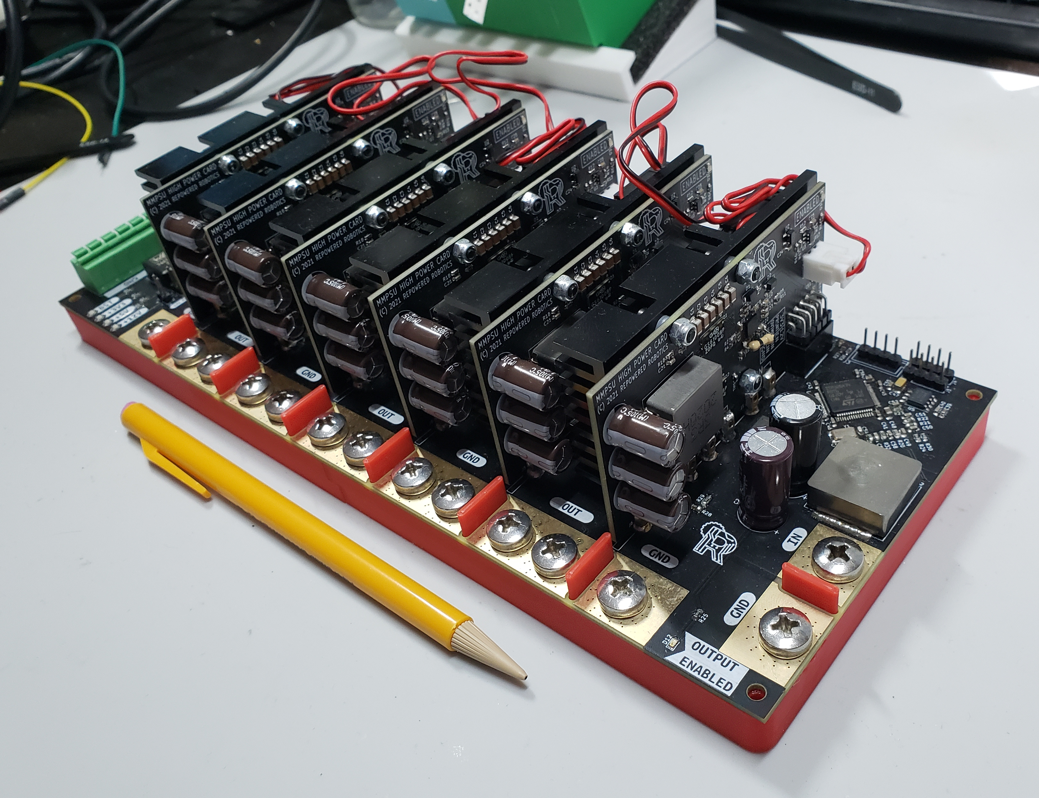
The Modular Multiphase Power Supply Unit with 6 power cards populated.
Theory of Operation
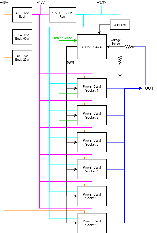 On the right you can see a block diagram of the MMPSU concept.
At it's core, the system is controlled by an STM32G474 microcontroller. The reason for this choice is because it has a so-called high-resolution timer which allows 6 channels of 16-bit precision PWM at relatively high frequency. The inner workings of the HRTIM are interesting on their own, but this article focuses on the high-level usage of the HRTIM in this project.
The idea is that each power card is a module that can be inserted into a motherboard, which handles control of the power cards and production of various power rails. All analog-to-digital conversion is done using the built-in ADC's in the STM32G474. This allows tight integration between the ADC sampling and control of the power stages. The outputs of the cards are bussed together to form a single output rail, and the microcontroller samples this and controls duty cycle accordinglly.
The device can be supplied with an absolute max voltage of 60V, and probably as low as about 18V. The output is adjustable from ~5V to ~24V. The device is modular, meaning between one and six cards can be populated.
Power Cards
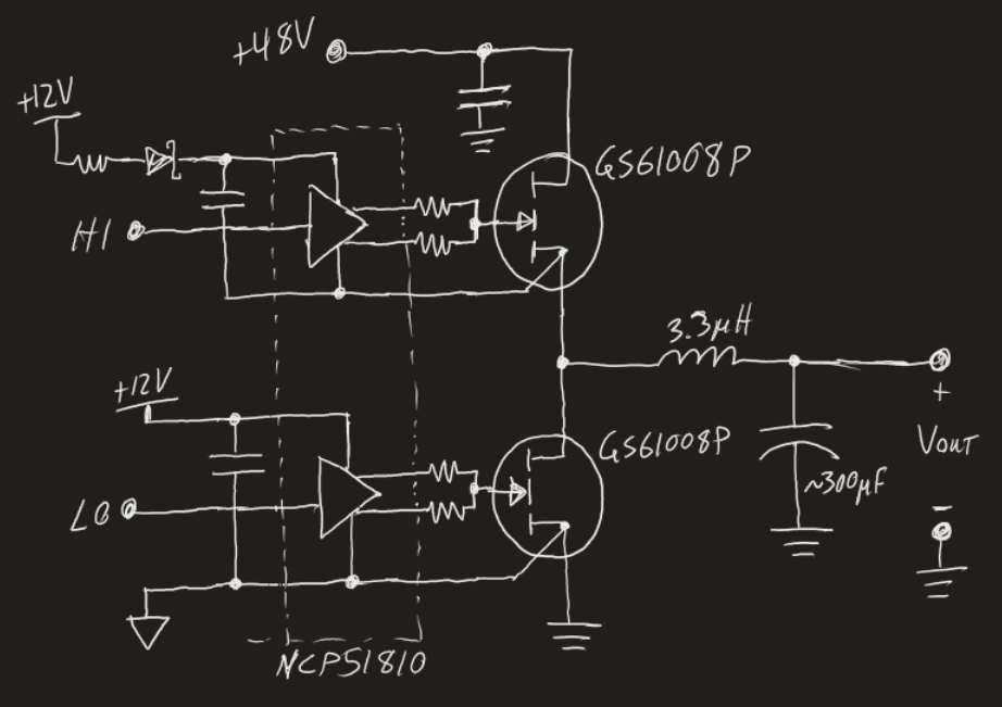 Each power card is effectively a synchronous buck converter, designed to handle ~30A continuous output current. The left-hand schematic shows the general concept of each power card. The synchronous buck stage is built around two enchancement mode GaN HEMT's made by GaN Systems - the GS61008P, and the onsemi NCP51810 half-bridge driver. We selected a pretty beefy 3.3uH inductor from Vishay, and (x3) 100uF electrolytic caps at the output.
The capacitor selection was made carefully, since we need capacitors that can handle the ripple current, which ends up being about 3A. We chose capacitors that were rated for over 1A RMS ripple current at 100kHz.
Phase Current Sensing
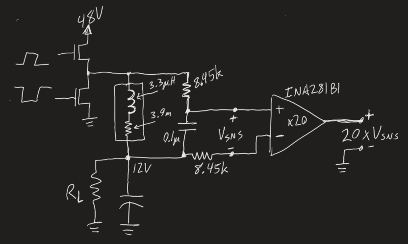 Each power card uses so-called "lossless current sensing" to report the phase current to the microcontroller. I came across this in a youtube video by Sam Ben Yaakov - see here. Sam covers a few other current sensing methods in that video, but this is the strategy I settled on.
Why is phase current sensing important you ask? The short answer is that there's a very real possibility of inbalance of current in different phases. If we ran all phases at the same duty cycle, there's no way to guarantee that the average current in any one phase wouldn't drift down to an average current approaching zero, leaving the other phases to handle all the load current (due to parasitic resistances). So we sense the current in each phase in order to balance the load current between the populated phases.
The INA281 with 20 V/V gain has a rated bandwidth of about 1.3MHz. With our switching frequency of ~1MHz, these amplififers are close to their maximum, and don't quite reproduce the waveform exactly, but they still report the lower frequency current measurement, which is more important anyway for our application.
Over-Temperature Sensing
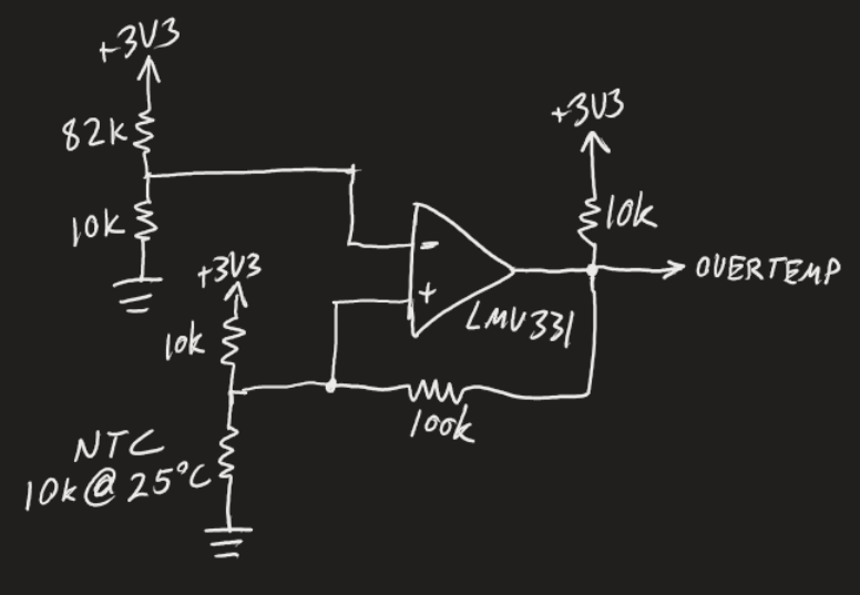 From the very beginning of the design process, it was clear that we would have to dissipate quite a bit of power on each card (over 20W), so we figured it would be prudent to add in a sort of over-temperature signal to the microcontroller so that different phases could be shut off if they begin to get too hot. This was realized by placing a surface mount NTC thermistor close to the low-side GaN with a simple comparator circuit to send a signal when the thermistor reaches about 90 degrees Celcius.
Digital Control with the HRTIM
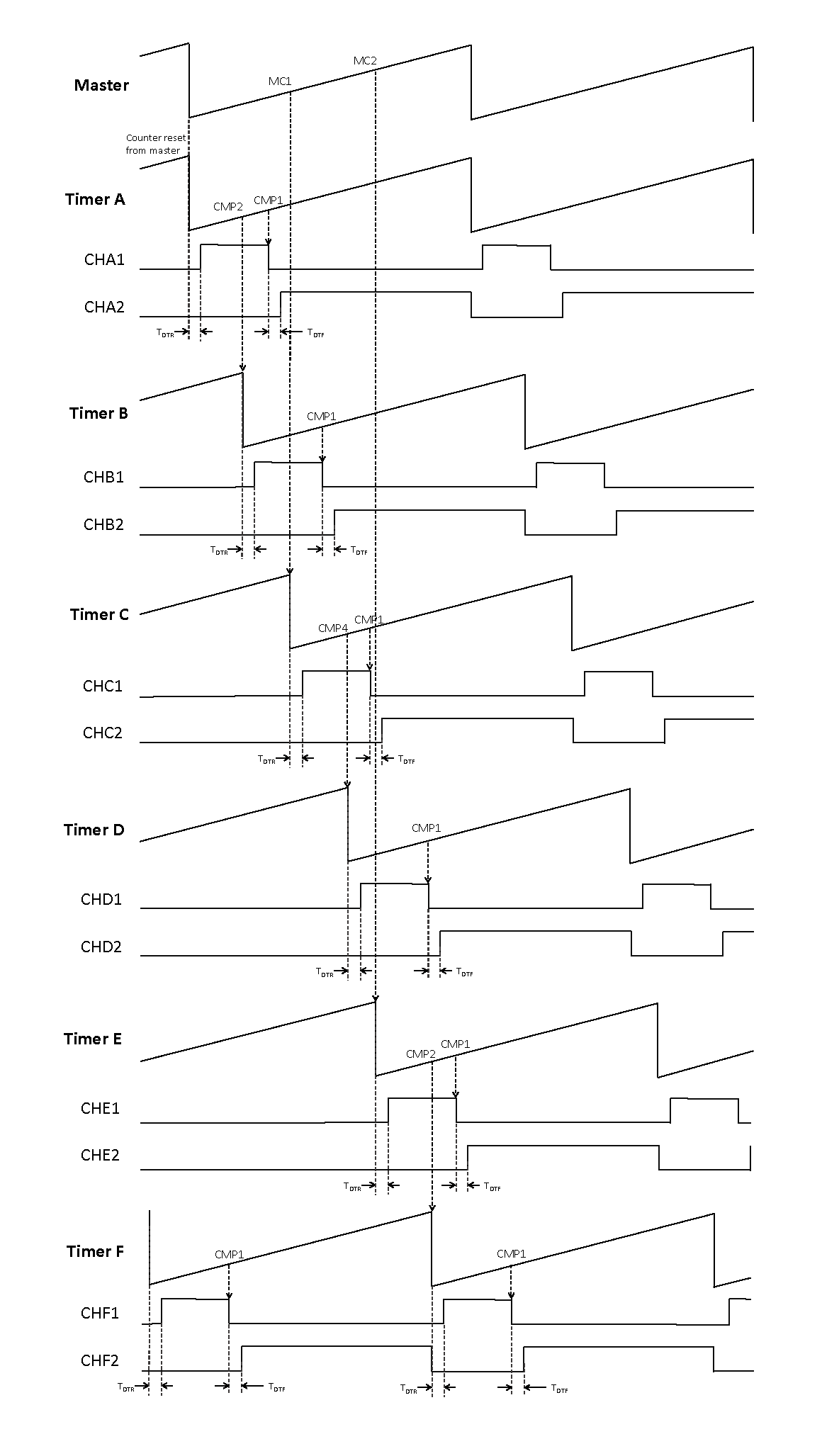 The high-resolution timer included in some STM32 microcontrollers is really a thing of beauty. Other microcontrollers have similar features, but the STM32 variants are the ones I've worked with. On the left you can see a diagram of how we're controlling the timers and the outputs. Since the master timer, and in fact all the timers, have only 4 compare registers each, I couldn't trigger the reset of all 6 timer channels at different phase angles from only the master timer. So I devised the more complex scheme you see there. Our system operates with a switching frequency of about 1MHz. As it shakes out, our resolution of control over the duty cycle is about 0.018% - plenty of precision for this application.
My starting point was the HRTIM Cookbook application note, which has a simple multiphase buck example and a synchronous buck example. Basically I had to merge the two and expand the concept to accomodate up to 6 channels.
Our voltage mode control loop ended up being pretty robust and stable without too much messing around. It's a PID controller, except without a derivative term, so it's really a PI controller. The PI subroutine and adjustment of the duty cycle occurs on the "Repetition" callback, which basically means our interrupt service routine is called every "N" many cycles of the HRTIM master timer. In our case, we chose N=24 after some trial and error.
The sampling of voltage and current is done sychronously with the HRTIM waveform. Samples are triggered with spare compare events and are transferred to RAM using the DMA controller. That took some messing around to get working. But once you know which settings to set to what, it all works out. The timing of these ADC sample triggers is important, as we want it to occur when there is not switching activity of the power stage, because that would introduce some noise and such.
I2C Interface
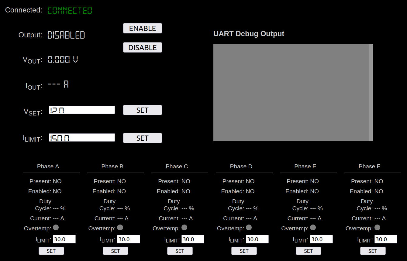
The device can be controlled, and performance information read back, over I2C. The I2C is handled with a channel on the DMA controller. I also wrote a little web application intended for a raspberry pi that gives us a nice user interface to control the MMPSU. Below you can see a picture of the web app, not doing anything, and not displaying all that well in Firefox.
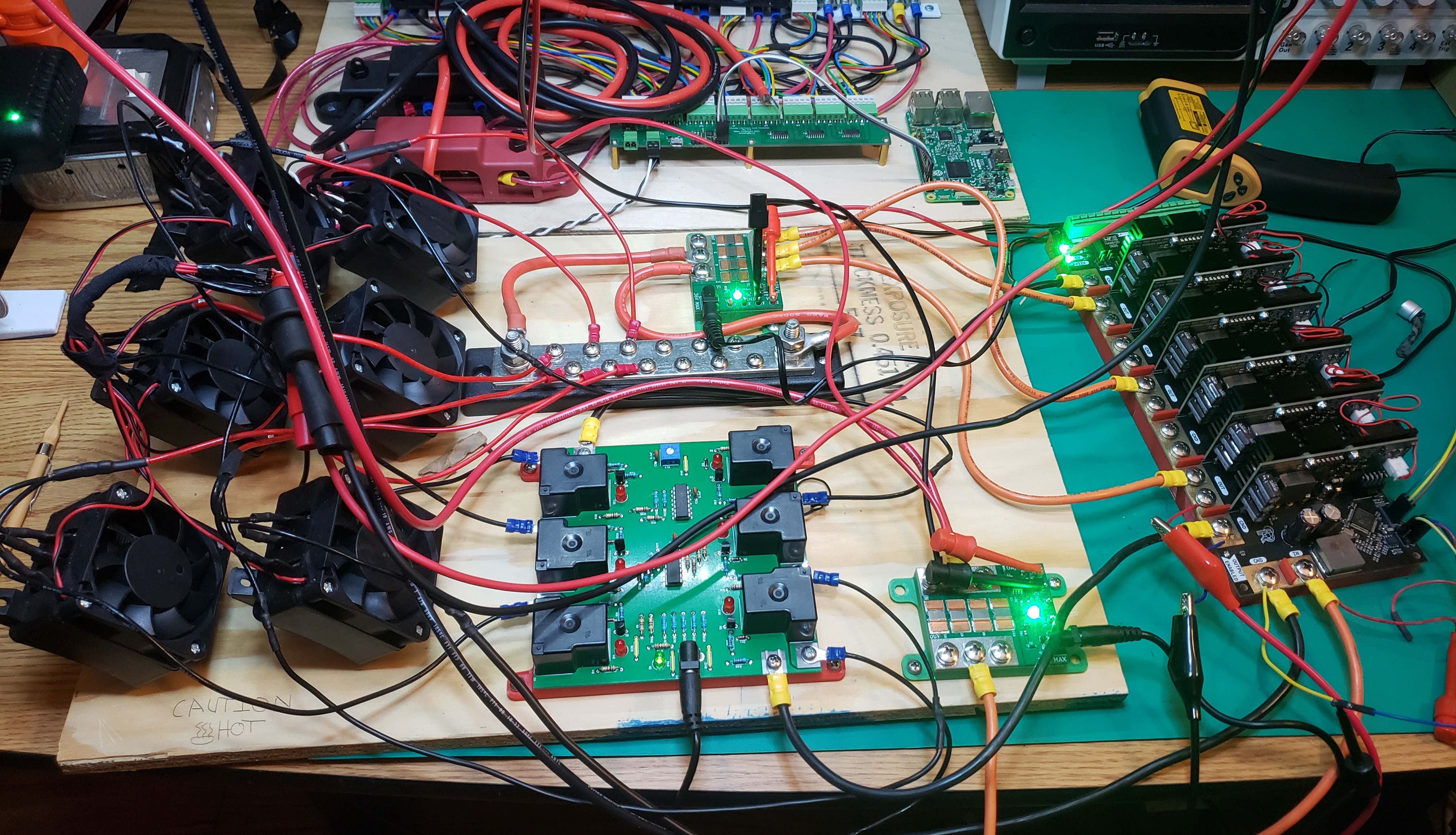
Testing and Results
At the time of writing this, we've tested it up to nearly 1000W output (12V @ ~80A). The heat produced was not at all concerning and it bodes well for cranking the power up. For a load, we are using six 12V 150W(ish) PTC heaters we bought from amazon. Thus, our main limitation at the moment is how many heaters we have. Fortunately they are relatively cheap and we can buy more. Below you can see our test setup.