Tesla Coil
My experiments with Tesla coils
Overview
I got interested in builing Tesla coils when I saw YouTuber ElectroBOOM's videos on Tesla coils. I was also influenced by the OneTesla design (which ElectroBOOM reviews on his channel). What I wanted was a circuit that would play high fidelity music, similar to ElectroBOOM's design and unlike the OneTesla design. The driver needed to be solid state, and naturally I wanted the biggest arcs possible.
My tesla coil driver is a single resonant solid state driver. It also seems accurate to me to call it a continuous wave type driver, as it drives the primary with a continuous AC voltage (although not a clean sine wave). My primary requirement for the control circuit was that it shall lock on to the resonant frequency of the secondary coil. ElectroBOOM notes that the lack of this feature is a shortcoming of his design. The OneTesla design also lacks secondary feedback, instead opting for a primary LC circuit that resonates close enough to the nominal resonant frequency of the tower.
The Driver Circuit
Concept of Operation
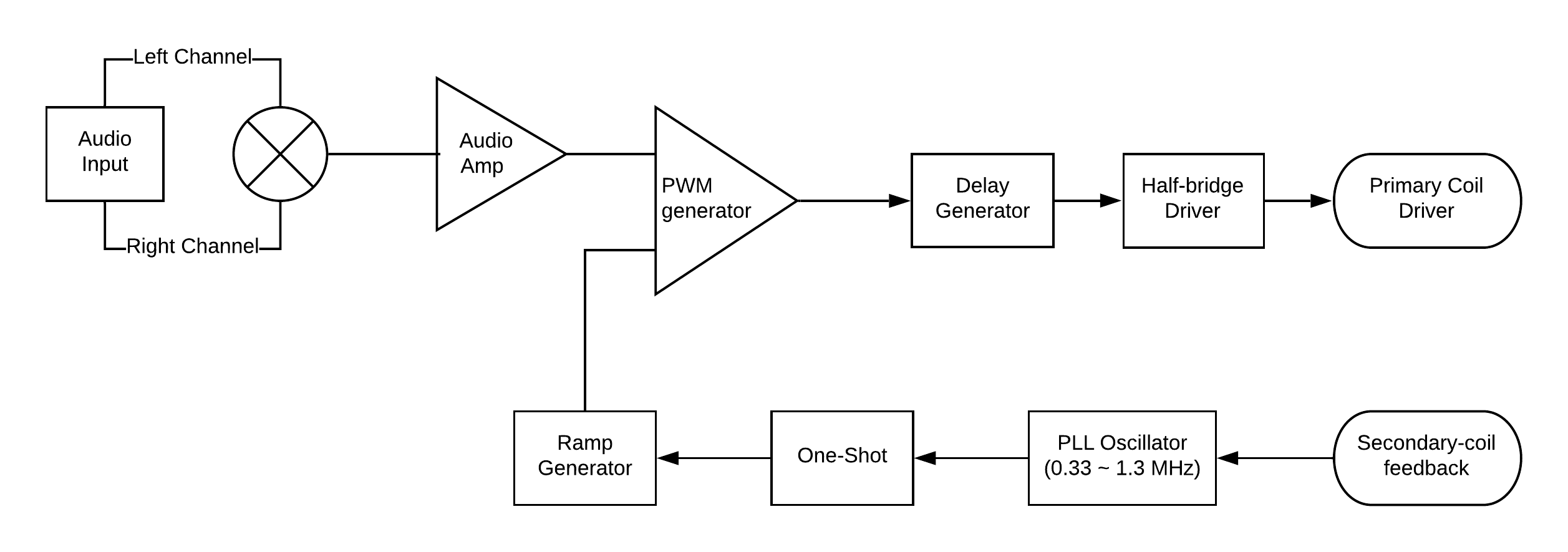
Block diagram of the driver circuit.
When an electrical arc is produced, it heats up and ionizes the air in its path creating a near vacuum. When the arc stops, the vacuum collapses. This cycle repeats, creating pressure waves in the air. By modulating the power of the arcs at an audible frequency, we can create sound. From here, the block diagram mostly speaks for itself.
Below is a high level schematic of my circuit. Important thing to note: the half-bridge is driving an LC circuit, however it is NOT used as a RESONANT LC circuit. The half-bridge is switched at the resonant frequency of the secondary LC circuit - the purpose of the capacitor (we'll call it the coupling capacitor) is to simply pass the AC voltage produced by the half-bridge while blocking any DC that might occur (such as when there is no PWM input signal). In fact, if we were to drive that LC circuit at it's resonant frequency with the half bridge, we would indeed get a large (desirable) voltage on the primary, but would swiftly destroy our half-bridge. When this LC circuit is resonating, the voltage across the primary is reaching several kilovolts in amplitude, making the voltage across the coupling capacitor also several kilovolts and allowing large current to flow through it when either FET is on, causing our FET's to experience very high current, so you want this LC circuit's resonant frequency to not be reached by the control circuit. Of course, I'm living life on the edge with my LC circuit's resonant frequency at ~570kHz, but all my coils tend to resonate at less than 500kHz. Fingers crossed.
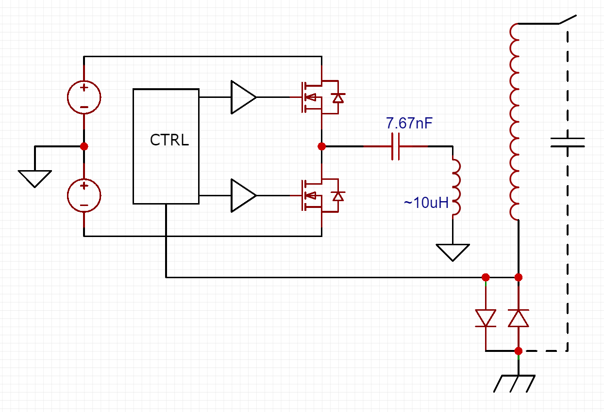
High level schematic of my driver circuit.
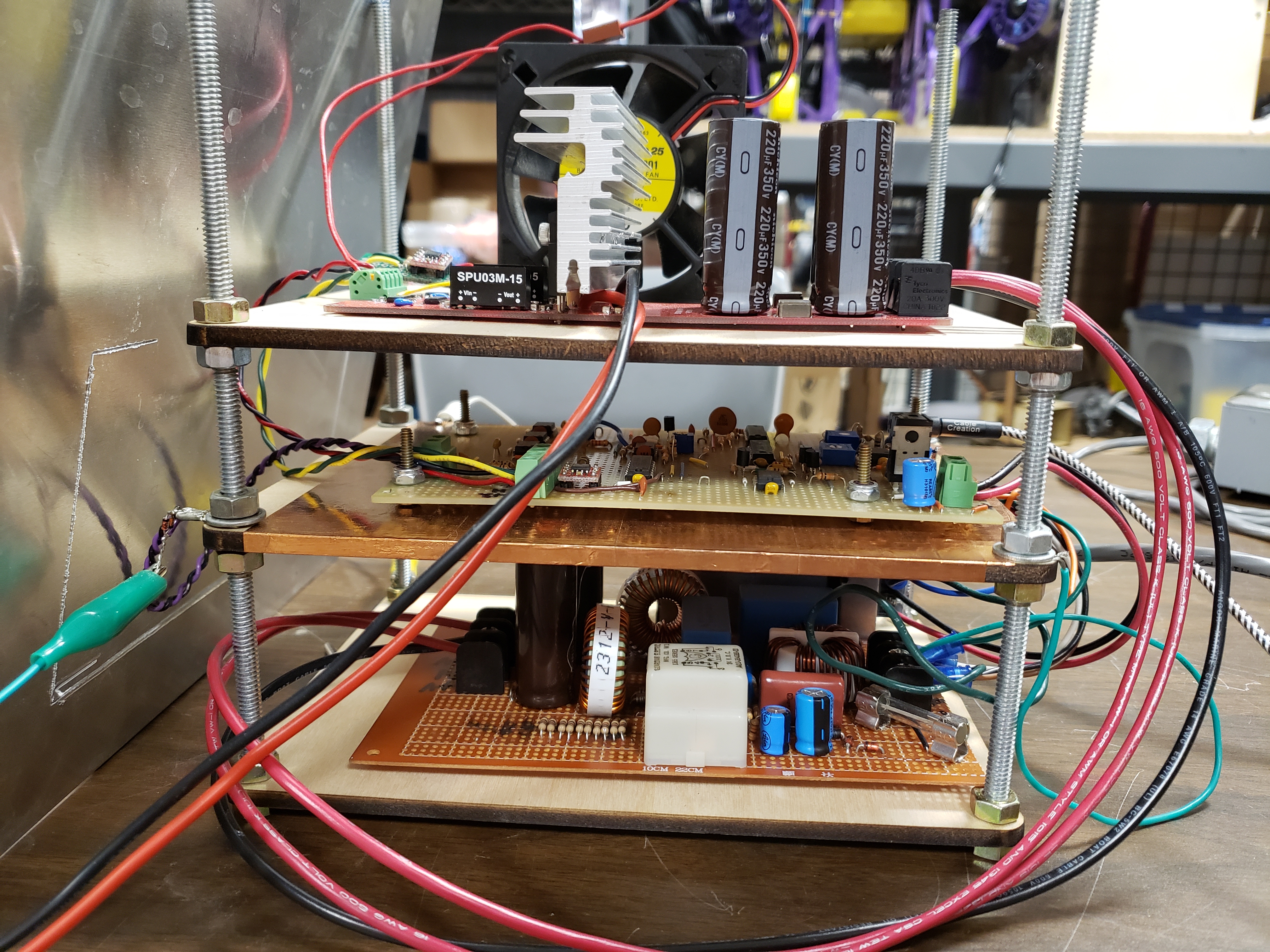
Detailed Schematics
Following are the detailed schematics of the entire driver. I split it into two boards–the audio (control) board and the driver board. The audio board takes audio input and feedback from the secondary coil and produces the PWM signal to send to the driver board. I use CAN bus transceivers to send and receive the PWM signal because CAN is robust and fairly immune to EMI (which there will be much of when running the coil :) ). I also had a few SN65HVD1050's lying around, so it was a natural choice.
Audio Schematic 1 of 2
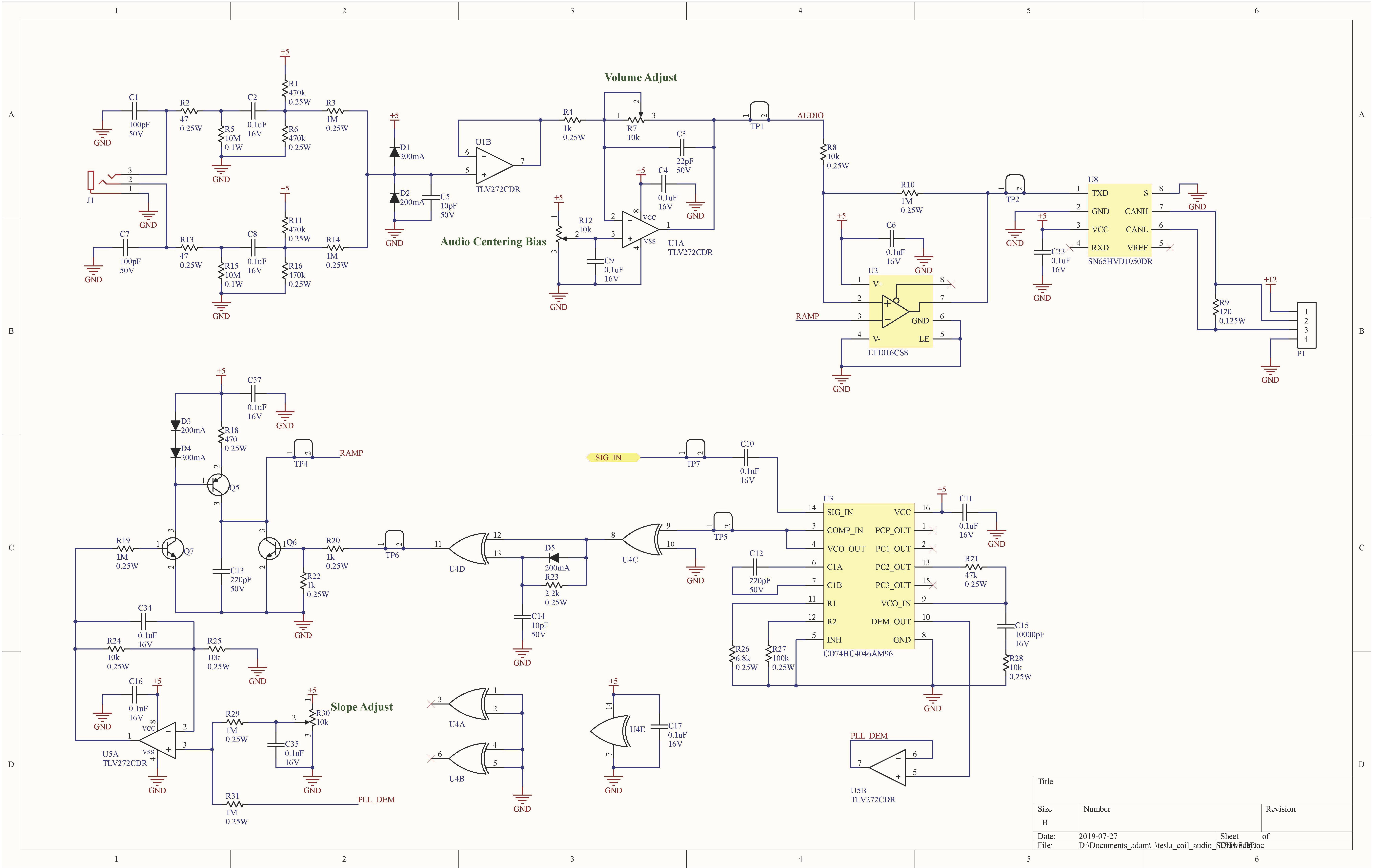
The ramp generator is based on a basic BJT current source. But I couldn't use a fixed current source—remember that our frequency can change quite a bit, so to get the most out of our ramp function (and require less twiddling of the pots), I needed the slope of the ramp to change with the frequency. Luckily, the PLL has an output which is the voltage going into the VCO, thus a voltage that goes up with frequency. We basically use that voltage to feed current into another BJT, which controls the current source, and with just a little pot twiddling, you've got an OK frequency dependent current source.
Audio Schematic 2 of 2
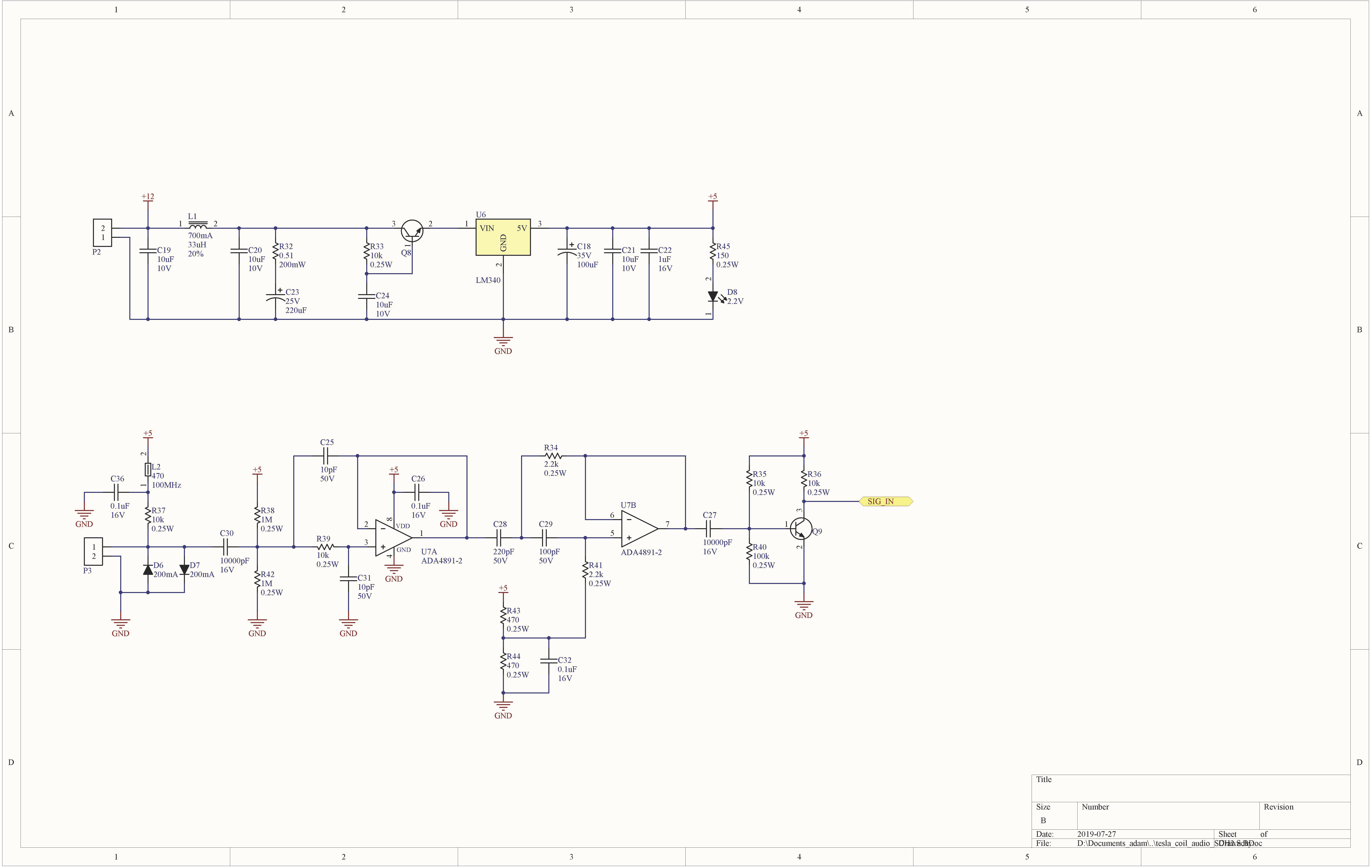
You'll notice I have some fairly elaborate filtering of the feedback from the secondary. It may be unnecessary, as I could likely get away with just capacitively coupling the signal from the diode clamp straight into the PLL. I'm not super cost or size constrained, so I didn't see a reason not to add some filtering. There will be broadband noise everywhere, and even if it wouldn't affect the PLL (I think it would) eliminating noise where possible will help the overall functioning of the circuit.
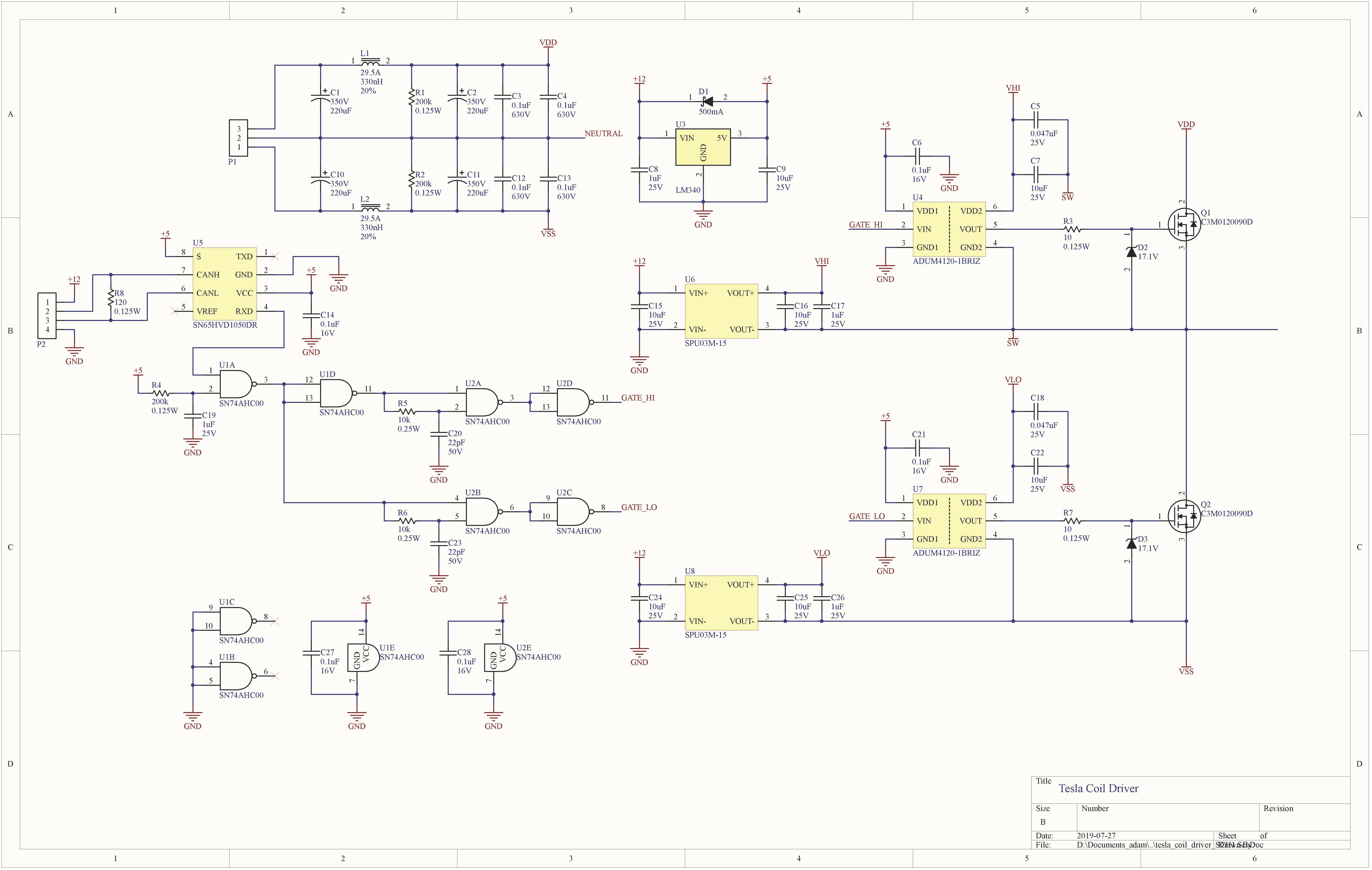
Driver Schematic
Power Supply Schematic
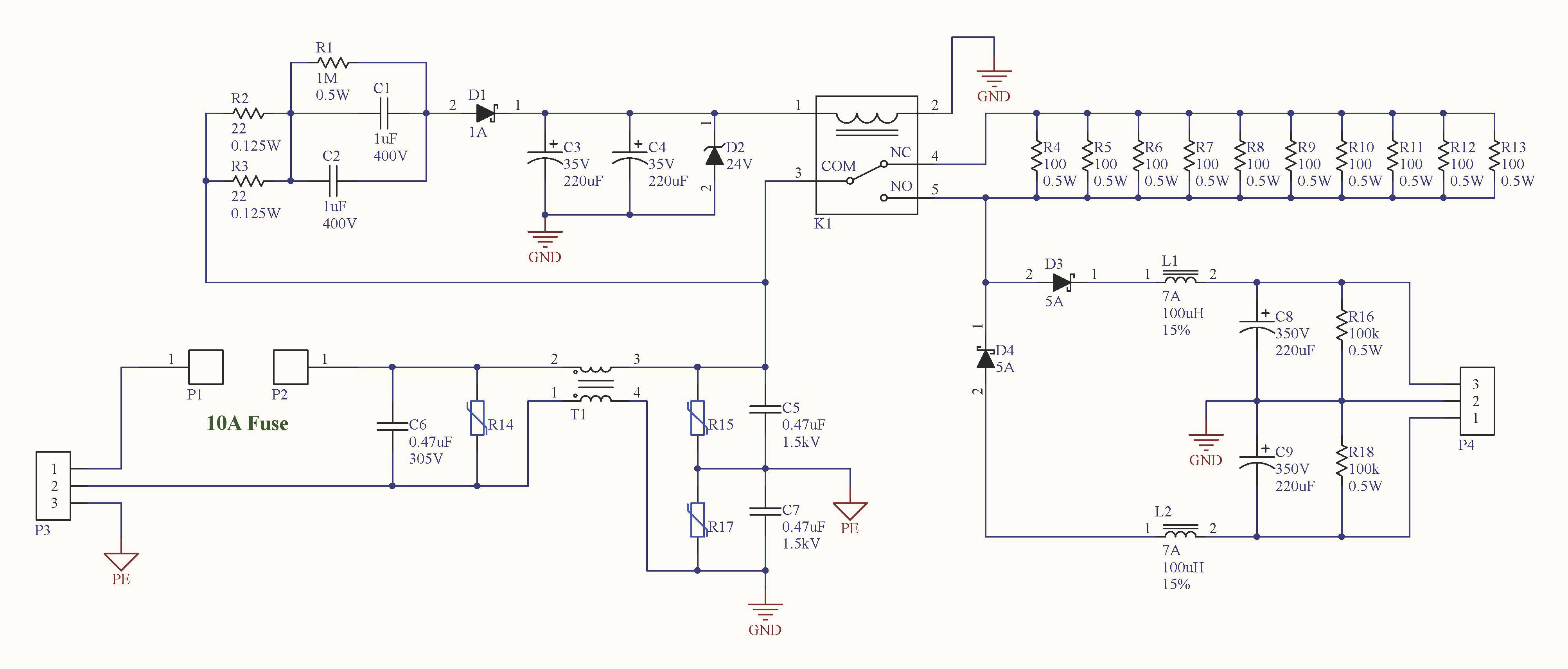
I elected to power the driver directly from the mains without a transformer. While this circuit won't pass UL testing, it makes the most of the voltage provided from the mains. It rectifies each half cycle into positive and negative 170V DC rails, which are fed to the driver board.
Choice of Switching Device
With all power electronics, the choice of switching device is critical. In more traditional Solid State Tesla Coil (SSTC) circuits, the switches exist to simulate a spark gap, and by firing the "spark gap" at audible frequencies, tones can be produced. Usually, designers choose IGBTs for their ability to withstand high voltage and relatively high current, plus the insulated gate is a nice feature. IGBT's are somewhat slow, and generally good for sub-200kHz switching. For my continuous wave design, however, I need to switch the half bridge at the resonant frequency of the secondary, which is typically between 300 kHz and 1 MHz or more (although all my coils resonate below 500kHz). This requires fast switches, which means MOSFET's. MOSFET's are notoriously sensitive and easily destroyed, so careful design is a must. My first choice was to use Silicon Carbide (SiC) MOSFET's, which can withstand voltages comparable to IGBT's, have very low gate charge (10's of nano-Coulombs), low RDS(ON), and nice thermal properties. My first choice was the Cree/Wolfspeed C3M0120090D, but I later switched to the C3M0065090D in favor of its lower RDS(ON).
Driving the MOSFET's
For driving the gates, I chose the ADUM4120-1BRIZ isolated gate driver. To provide the two isolated floating power rails, I chose the SPU03M-15 15V isolated DC-DC converters. I also put a 17V zener diode from gate to source on each FET to prevent fast transitions or transients from shooting through the gate-drain capacitance and blowing out the gates. The PWM signal comes from the separate control board. For reliable transmission of this signal, I settled on using a SN65HVD1050 CAN-bus transceiver. The PWM signal is then translated into the drive signals for the FET's with a few 74AHC00's and some RC networks to provide delay/dead-time between switching each FET.
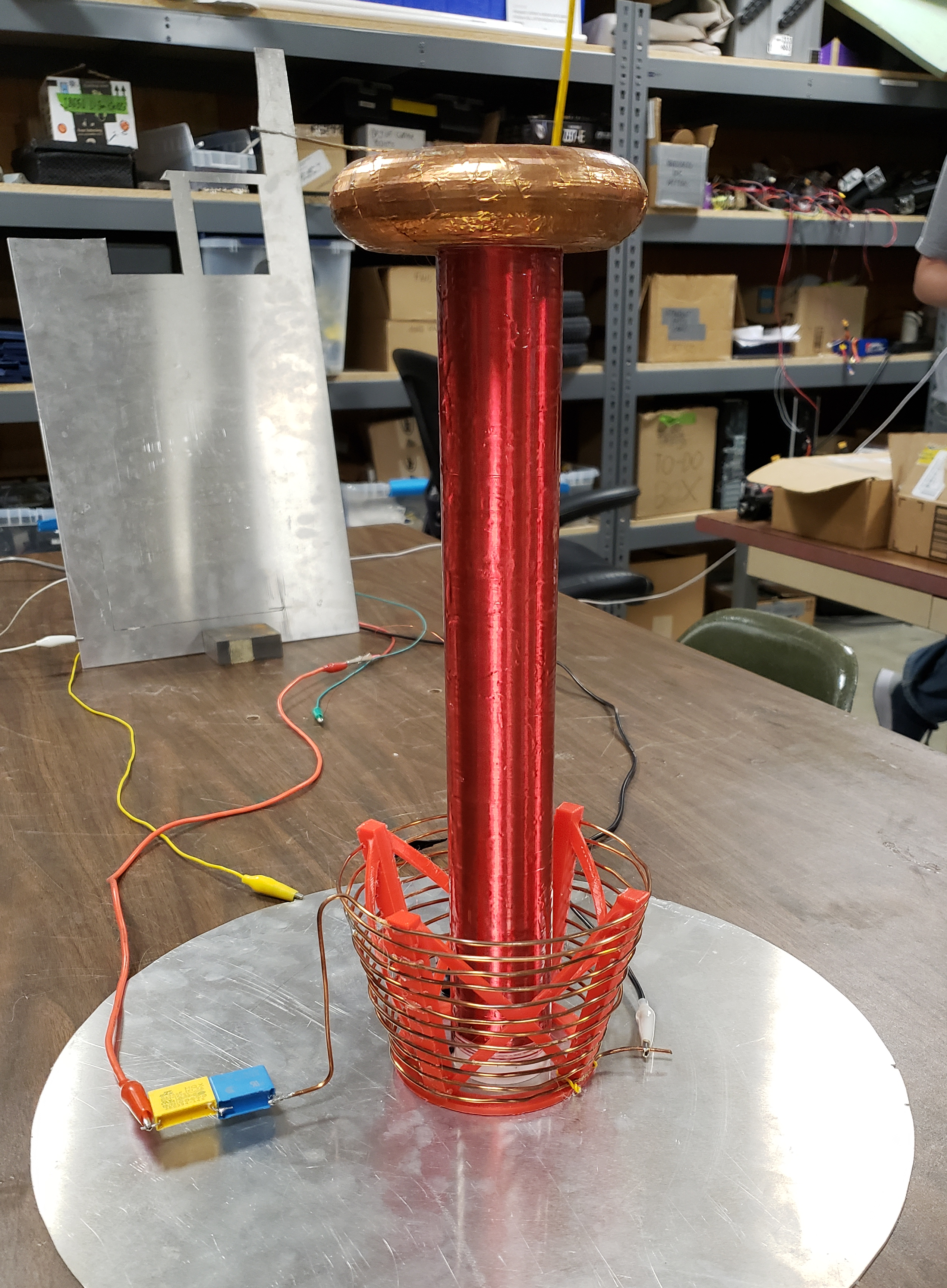
The Coils
The main principle driving my coil designs is the following: more turns on the secondary means bigger arcs. Which is, all else being equal, true. But with more turns comes lower resonant frequency, so I had to be careful that the resonant frequency would stay within my 330kHz - 1.3MHz range. For mk1, I really did no calculations. I wound it up, made the torus, and tried it out. For mk2, I was careful to design it to have the most turns possible while staying above the 330kHz cutoff of my circuit. For mk3, I decided I wanted the biggest arcs possible, and have resolved to build a different circuit for that one (likely not musical).
I used schedule-40 PVC pipe as the form for each coil. For mk1 and mk3, I used 2" nominal diameter pipe. For mk2 I used 1.5" nominal diameter pipe. For calculating the self inductance of a coil, I use the standard formula for the inductance of an air-core solenoid:
$$ L = \frac{\mu_0N^2A}{l} $$
The magnetic permeability of the PVC seems to have a negligible effect on the inductance of the coil.
For calculating the capacitance due to the top load, I found you can get a close approximation using the formula for the capacitance of a disk: $$ C = 8\epsilon_0r $$ For a better approximation, you can take a look at this handy Capacitance of a Toroid Calculator from deepfriedneon.com. Lastly, there is the much more difficult to calculate parasitic capacitance of the coil. You can assume that it will be on the order of 1 to 2 pF. Really, the point of these calculations is make sure the resonant frequency will be in the right ballpark.
| Coil Iteration | Height | Diameter | Wire Gauge | Turns | Self Inductance |
|---|---|---|---|---|---|
| mk1 | 35 cm | 6.06 cm | 30 AWG | ~1500 | ---- |
| mk2 | 35 cm | 4.83 cm | 34 AWG | ~2000 | ~40 mH |
| mk3 | 58 cm | 6.06 cm | 34 AWG | ~3250 | ~66.5 mH |