Dual-Phase Synchronous Buck - 1000W
(IN PROGRESS) Building a digitally controlled dual-phase synchronous buck converter
My university robotics team, CWRUbotix does frequent bench-testing of our robots. So I've taken it upon myself to build an adequate bench power supply. It needs to be variable from less than 12V to at least 48V and supply as much as 1000W. That's a lot of power supply. I found that sourcing beefy transformers is pretty hard, so I decided to start with off-the-shelf AC-to-DC power supplies. Then I would implement some kind of buck converter. For 1000W, I knew it would have to be multiphase. I started with the following basic concept:

12V power supplies are easy to come by ($18.88 each on Amazon>), so I figured I'd stack up 4 of them to acheive the 48V required (I trim each one up to 12.5V to account for losses). After some back-of-the-envelope calculations and much deliberation, I decided on two phases. I also decided to make it a synchronous topology because I need efficiency (even 5% loss at 1000W would be 50W to dissipate).
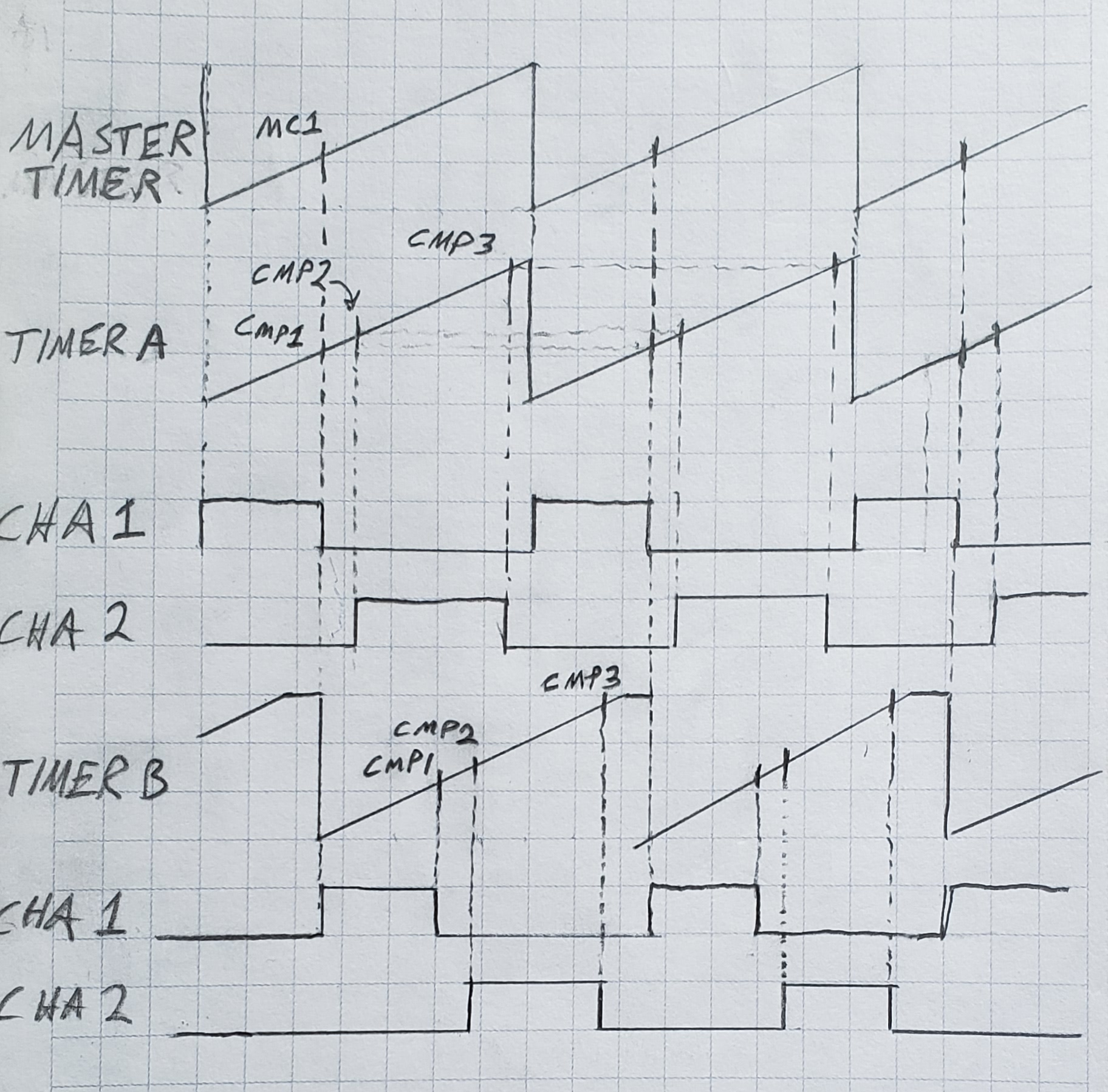
Next, I decided I would make it digitally controlled. The main driver behind this was discovering some STM32's have high-resolution timers. Their inner workings are pretty neat and they're highly configurable. The bottom line is they allow high resolution PWM even at relatively high frequency (100's of kHz in this application). My jumping off point was this application note from ST: AN4539 - HRTIM cookbook. It has examples for a single phase synchronous buck and a multi-phase asynchronous buck, but some augmentation was needed for my application, as I will discuss shortly.
Design Process
For the schematics, jump on down to here.
Power Section
To me, the most critical choices in this design were the switching transistors, inductors, and switching frequency. Finding suitable magnetics was the toughest part to me, so that's where I started. I wanted the largest inductance possible (to keep the switching frequency as low as possible) with the highest saturation rating possible. I identified a 6.8uH inductor with a 32A saturation current. That would do it.
Analog Front-End
Another important choice was how to handle the analog front end. Using the built-in 12-bit ADC's and basic feedback circuitry, it would allow at best about 12mV resolution. With some oversampling, that could be enough to make me happy. But I figured as long as I'm building this from scratch, I might as well make it nice. Although a 16-bit ADC would be sufficient, I elected to use a 24-bit ADC, the AD7172, because why not. It's highest sample rate is 31.25 kSPS, and at that rate about 20 bits are noise free. If this unit does nothing else, it will measure voltage and current really well.
Major Component Summary
| Component | Description | Manufacturer | MFG Part # |
|---|---|---|---|
| Microcontroller | IC MCU 32BIT 64KB FLASH 64LQFP | STMicroelectronics | STM32F334R8T6 |
| ADC | IC ADC 24BIT SIGMA-DELTA 24TSSOP | Analog Devices | AD7172-2 |
| MOSFETs | MOSFET N-CH 100V 131A D2PK TO263 | Vishay Siliconix | SUM70060E-GE3 |
| Inductors | FIXED IND 6.8UH 36A 3.1 MOHM SMD | Bourns | SRP2313AA-6R8M |
| Output Caps | CAP ALUM 220UF 20% 160V RADIAL | Nichicon | UCS2C221MHD1TN |
Control Waveforms