Multiphase Forward Converter - 1000W
(IN PROGRESS) Building a digitally controlled multiphase isolated forward converter
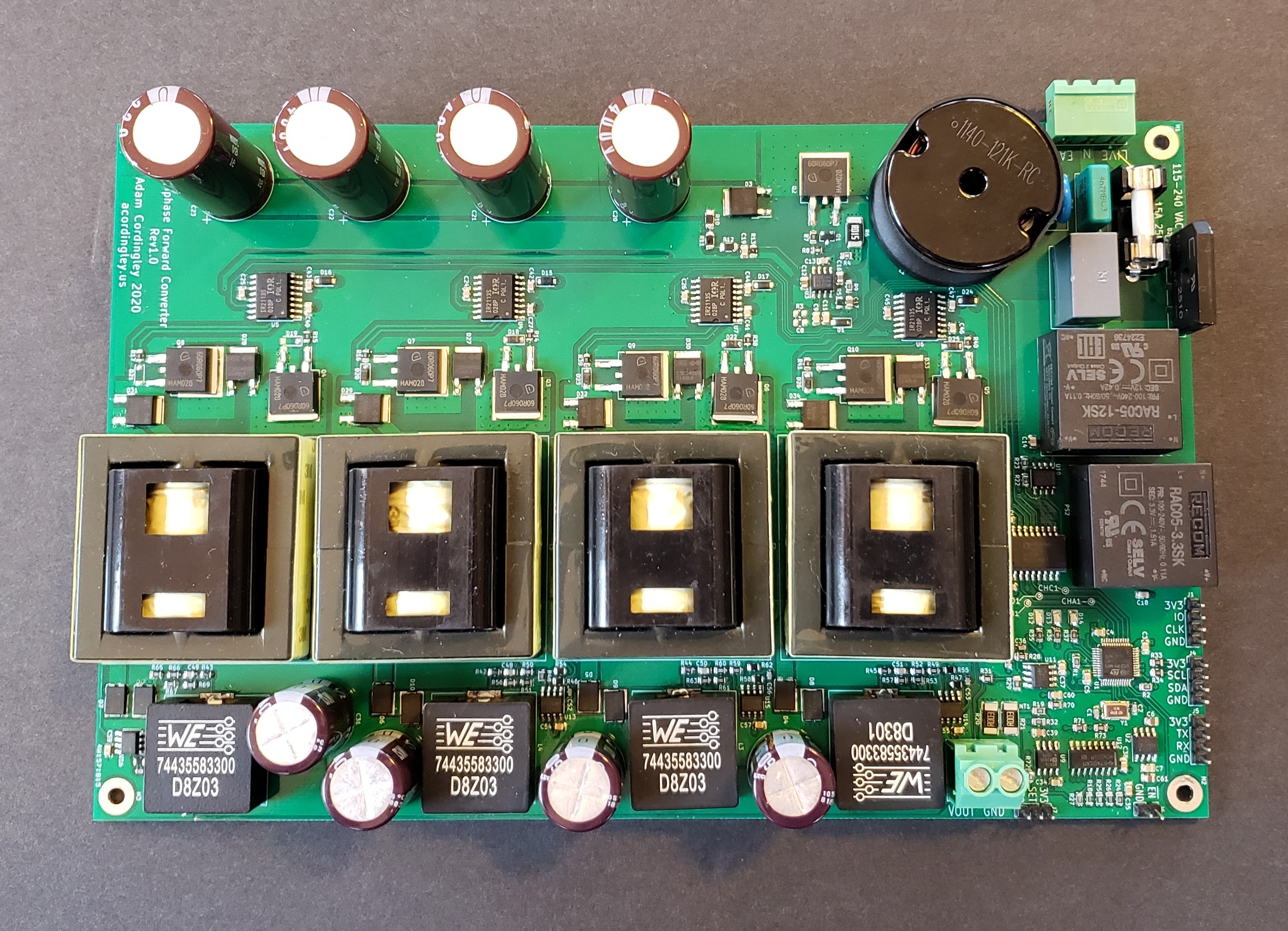
Top view of assembled board
Links
Overview
What I'm building is a digitally controlled multiphase isolated forward converter with active power factor correction. This approach to the 1000W power supply was the approach I wanted to take from the beginning. What was holding me back was limited availability of high power SMPS transformers from distributors. It was looking like I would have to order some custom transformers when I happened across some transformers made by Wurth, being sold by both Mouser and RS Components, rated for about 250W. They were a lucky find. I ended up buying 8 from RS Components, since Mouser had a minimum order of 15.
Topology
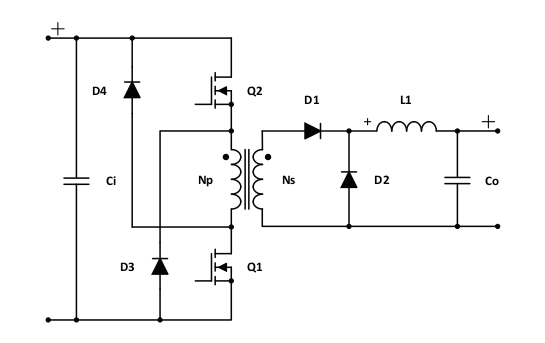
Single phase two-switch forward converter[1]
Digital Control
My choice for the controller was an ST part - the STM32F334C8[2] - which has one of their high-resolution timer blocks. I opted to use one of the built-in 12-bit ADC's for feedback, because they're fast and can be tightly integrated with the HR timer. This meant the feedback and control would be on the secondary side, and I would send the digital control signals across the isolation barrier to the primary side.
The control of an isolated forward converter is a lot like a buck converter (which is a type of forward converter). There are some differences, but let's run with this comparison for a moment. Imagine you take a buck converter and replace the input power supply and MOSFET with the secondary of a transformer plus a diode. Everything after that is the same (inductor, freewheeling diode, capacitor). Everything before that is for switching the primary of said transformer. The control, incidentally, is almost the same. The main difference is a new constraint - that the duty cycle can't be greater than 50%. In short this is because the transformer's primary needs to be allowed to fly back in order to demagnitize the core. The amount of time it needs will be equal to the on-time of the switches.
Results
Testing and firmware refinement is in progress!
Schematics
References
-
"Power Topologies Quick Reference Guide." ti.com. https://www.ti.com/lit/ug/slyu032/slyu032.pdf?ts=1607679033468 (accessed Dec. 12, 2020).
-
"Mainstream Mixed signals MCUs Arm Cortex-M4 core with DSP and FPU, 64 Kbytes of Flash memory, 72 MHz CPU, CCM, 12-bit ADC 5 MSPS, comparators, op-amp, hr timer." st.com. https://www.st.com/en/microcontrollers-microprocessors/stm32f334c8.html (accessed Dec. 12 2020).
-
"AN4539 Application Note HRTIM Cookbook." st.com. https://www.st.com/resource/en/application_note/dm00121475-hrtim-cookbook-stmicroelectronics.pdf (accessed Dec. 12 2020).