Thermal EMF in Current Shunt Resistors
A rarely-discussed error source in low-level measurements
Table of Contents
Backstory
My buddies and I had designed and built-up a USB PD power supply intended for modular sythesizers. To make it extra fancy, we decked it out with some gubbins for measuring the power draw, using the rather excellent INA236 from Texas Instruments. The core of the supply was just a few switch-mode converters followed by 10mOhm shunts which the INA236's measured across.
We had pretty much everything working, and the measurements under load seemed pretty good, until my buddy noticed some small errors showing up in the current measurement. With no current drawn from the +12V output, the INA236 was still reporting around 10 miiliamps. A similar situation on the +5V output. With the supply being capable of doing 4 or 5 amps at full tilt, 10mA seems like a drop in the bucket. But ... why was it showing up? With a 10mOhm shunt, that would mean there was 100μV being presented to the INA. Suffice it to say, the specs on the INA236 are pretty darn good, so there wasn't a smoking gun. So one Friday night I decided to get to the bottom of it.
You've already read the title, so you know where this is all going. Getting there was not quick or straightforward. As the night wore on I thought I was losing it. The clues weren't making sense.
Seebeck Effect
Those who have dealt with temperature measurement at all have likely encountered the Seebeck/Peltier/thermoelectric effect. It's the reason thermocouples work, and can be a source of errors in low-level measurements, or so the volt-nuts tell us.
In the case of current sense resistors, you may have encountered a diagram like this:
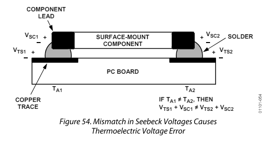
AD8552 datasheet page 16.
Ok, if the two leads of the resistors are at different temperatures, the differing metals produce thermocouple voltages that don't cancel out and you have error. But based on my testing above, it seemed like this was in the ~5μV region. Where was 100μV coming from?
This led me to think about differing metal-metal junctions inside the resistor itself. So I scanned the datasheet more carefully, looking for a thermal EMF specification for the resistor itself.
Datasheet Specs of the Shunt
The shunt we had selected was a 3W rated 2512 case code 10mOhm shunt - Bourns CRA2512-FZ-R010ELF. There's an interesting note at the top of its datasheet regarding thermal EMF.
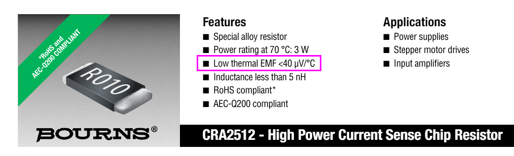
Highlight from the top of the datasheet on this particular resistor.
They say less-than 40μV/°C, but how much less? Maybe they don't know or can't guarantee, so I took it to mean "it could be as bad as 40μV/°C and with some significant variation." But I was on a mission to get an actual number. How bad exactly is it, and can it explain the error completely?
Experiment to Measure Thermal EMF Tempco
My plan was to somehow force a known (or at least measureable) thermal gradient across the resistor and measure the resulting voltage with the 34401A. I wanted to use an ice bath to create a known 0°C reference environment and dip one terminal of the resistor into that. Then dip the other terminal into a slightly warmer water bath, the temperature of which I would measure with a random type-K thermocouple and a DMM. (This is just what I had on hand, not super ideal.) And of course I'd have leads coming off the DUT to run to the DMM.
Copper is pretty conductive, thermally and electrically, so I grabbed some solid 12 AWG copper wire, cut two ~6cm legs, then soldered those to each terminal of the DUT. These legs would dip into the water baths and hopefully bring each terminal of the resistor very close to the temperature of the baths. I soldered on sense wires to these copper legs also.
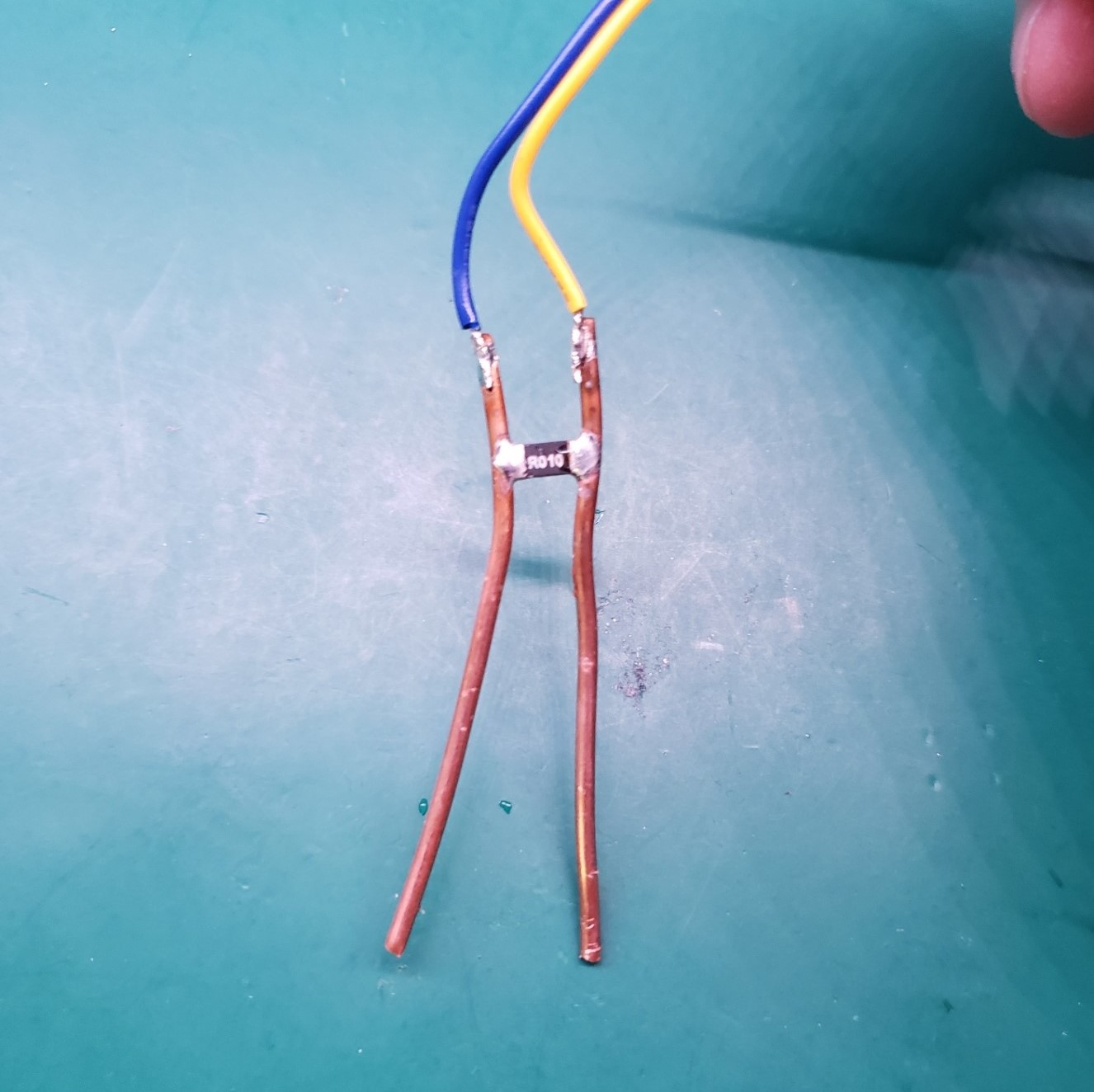
Resistor (DUT) with copper legs soldered on.
Next was making two small water baths: one with ice, the other with just water that had been in my refrigerator for awhile. I planned to have the baths and DUT in the fridge to control the ambient temperature, keeping it kinda stable and also kinda close to the temps of the baths and DUT to minimize heat flux into the DUT that would create more error.
Before actual measurements could be made, I needed to figure out what offset I was working with due to other metal-metal junctions in the system. So I dunked the whole DUT assembly into the ice bath, waited a few minutes, and took down the measurement. The 34401A reported about 5μV.
Taking an offset measurement by dunking the whole DUT assembly into the ice bath.
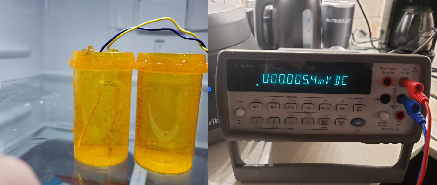
Finally I dipped each leg of the DUT into each water bath, waited a bit, and read off the measurements. The uncontrolled bath was reading about 8°C, and the voltage across the DUT was reading about 184.4μV. So this works out to a thermal EMF tempco of ~22μV/°C. Pretty believable given what the manufacturer says and based on the error we saw on the prototype.
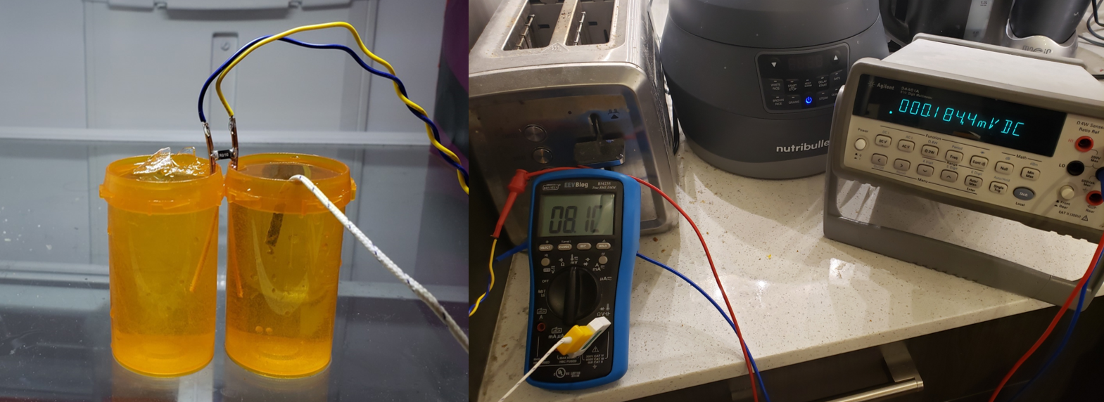
LEFT: DUT dipped into the two ice baths. A type-K thermocouple is probing the right-hand non-icy bath. RIGHT: The brymen is measuring the thermocouple. The 34401A shows 184.4μV measured across the DUT.